
Adampower
![]()

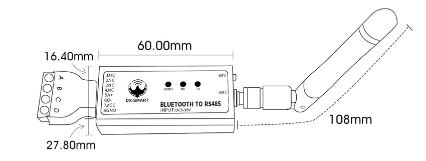
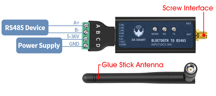
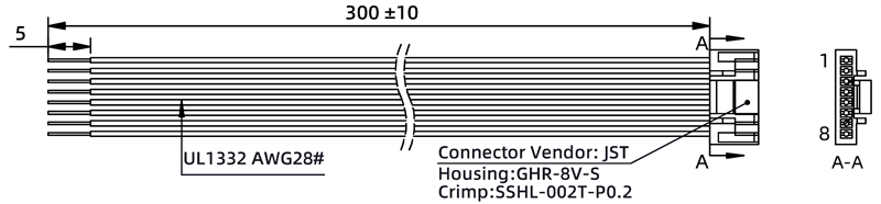
Industrial BLE5.1 Bluetooth to RS485 Converter Wireless Serial Port Adapter with Data Transparent Transmission.
1.Renesas DA14531 chip PA Amplifiers
2.Bluetooth BLE 5.1
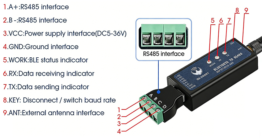
3.Support interfaces: RS485
4.Support ModBus protocol
5.Support communication between Android and RS485 Stepper Motor or RS485 Integrated Stepper Motor.
6.Support changing baud rates, baud rates support: 2400, 4800, 9600,19200,38400,57600,115200
7.External rubber stick antenna, Visual distance for communication with
devices:mobile phone:90m /PC:70m/ device to device:400m.
8.Support power range:DC5-36V
9.Device Size:60 * 27.8 * 16.4mm
10.Working temperature: -40 to 85°C
Module Serial Port Default Parameters:
RS485 communication port: default 9600 baud rate,
load capacity of up to 32 devices can be connected,
communication distance 1200 metres (9600bps).
Working mode: point-to-point half-duplex,
point-to-multipoint half-duplex, automatic direction
control, power supply 5V/1A.
Module BLE UUID:
SERVICE UUID: FFEO
NOTIFY/WRITE UUID: FFE1
WRITE UUID: FFE2
Baud Rate Switch:
Short press the KEY twice consecutively to switch the baud rate once, the number of times the blue light blinks represents the baud rate number.
The blue light blinks once baud rate is 2400, blinks twice for 4800, blinks three times for 9600, blinks four times for 19200,blinks five times for 38400,blinks six times for 57600,blinks seven times for 115200.
Blue light flashes <---> baud rate:
| Flash Count | Baud Rate |
|---|---|
| 1 | 2400 |
| 2 | 4800 |
| 3 | 9600 |
| 4 | 19200 |
| 5 | 38400 |
| 6 | 57600 |
| 7 | 115200 |
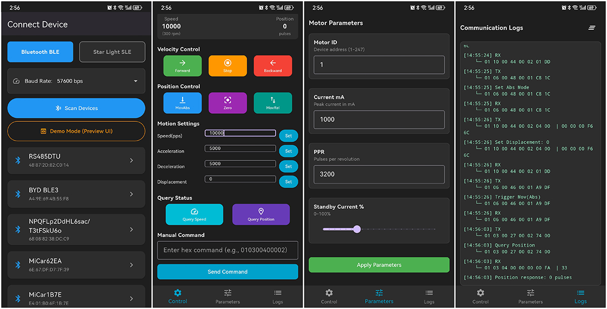
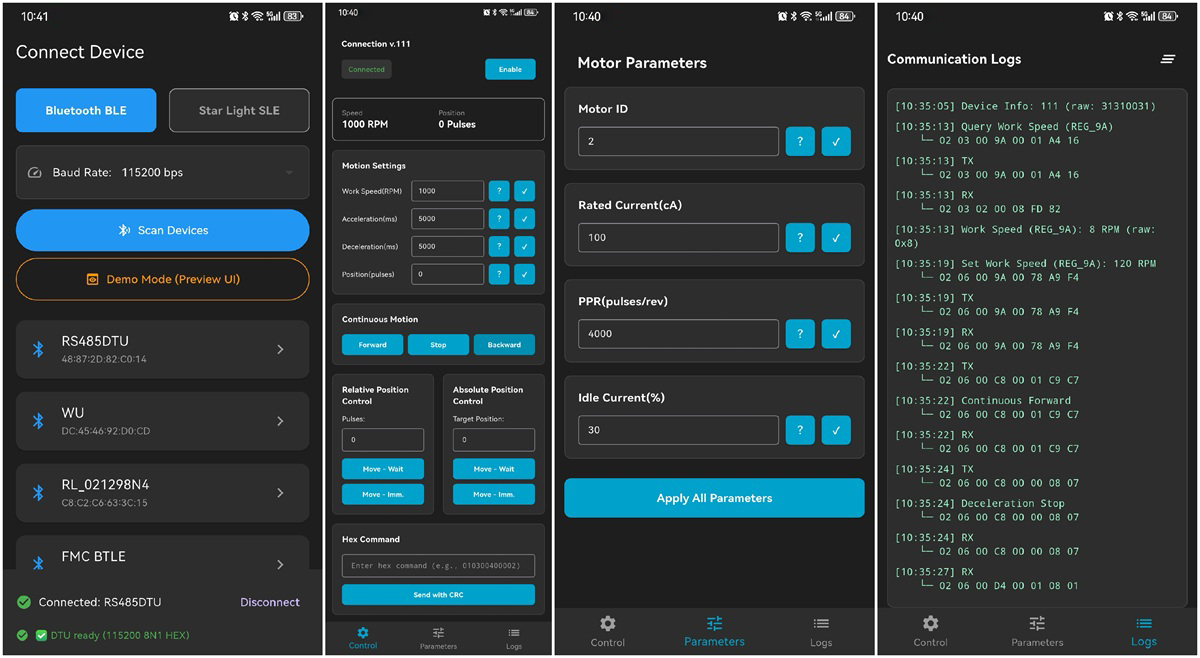
All controlled via Mobile Phone:
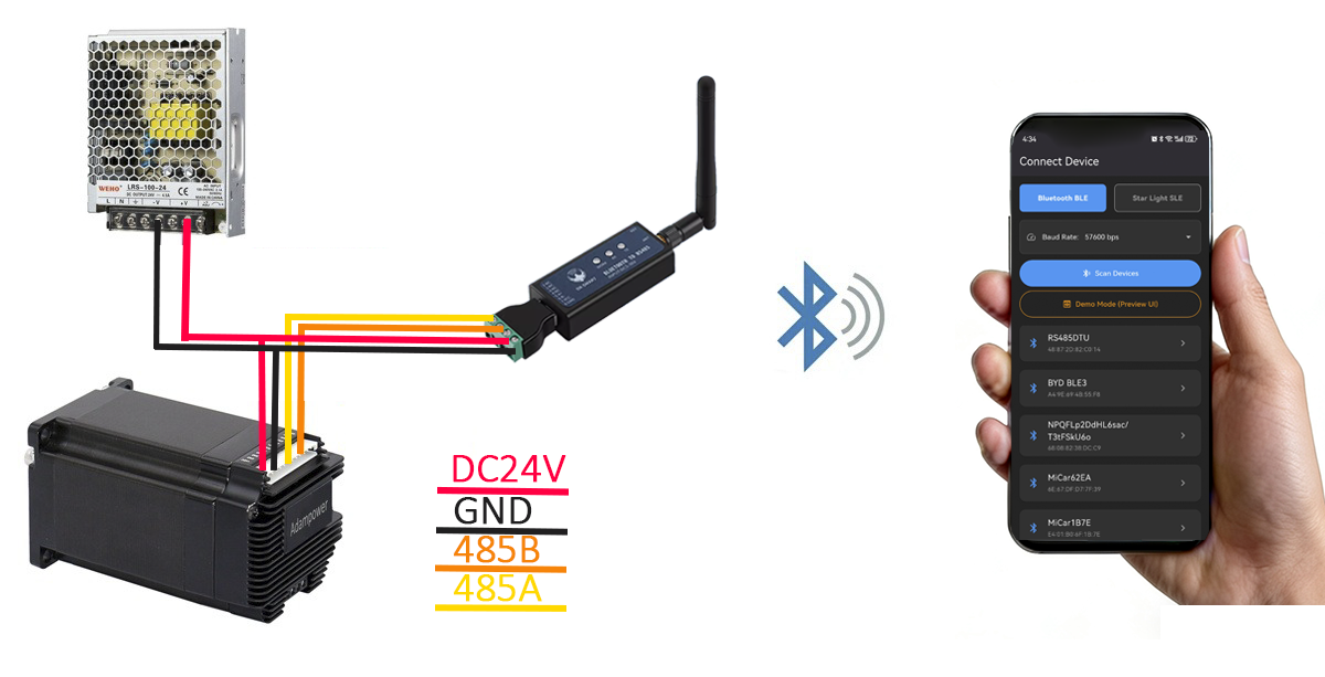
Bluetooth to RS485 Converter and Android APP designed for AR Series RS485 Integrated Stepper Motor.
 |  |  |
APP Screenshot
Download the Android APP
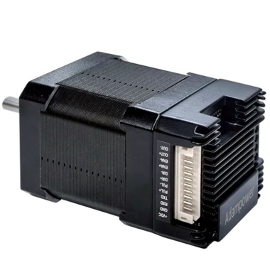
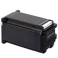
Bluetooth to RS485 Converter and Android APP designed for IG Series RS485 Integrated Stepper Motor.
 |  |  |  |
APP Screenshot
Download the Android APP
More Information on detail, please feel free to contact me 

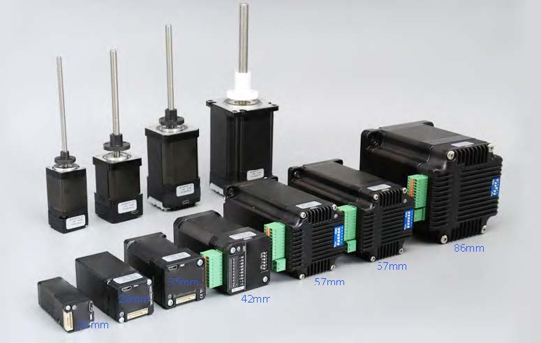
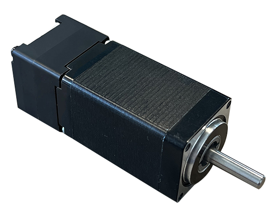
The IG8 series integrated motor is the perfect combination of drive and stepper motor,
which perfectly integrates stepper motor and drive technology, also built in 1000 line encoder,
it can save installation space, Simultaneously saving design and production costs,
supporting RS485 communication.
| Item | Specifications |
| Stepper Motor Size | NEMA8 |
| Encoder type | 1000 line encoder |
| Working voltage | 6~24VDC |
| Driver Current | 0.2-1.5A |
| Velocity range | Up to 3000RPM |
| Control Method | RS485, Pulse& Direction, Twin-Pulse, I/O, Built-in Program |
| Torque value | 0.08 - 0.24Nm |
| Nonvolatile storage | Configuration parameters are stored in FLASH inside the MCU |
| Protection | Overvoltage, undervoltage, overcurrent, open winding, position deviation |
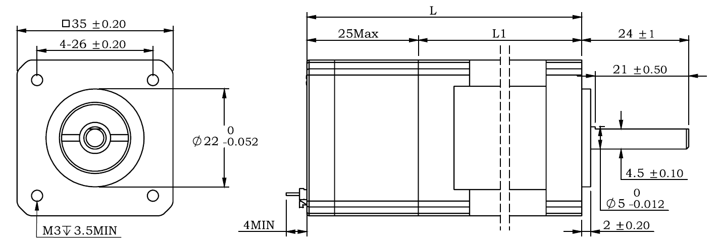
Motor Parameters
NEMA8 integrated Stepper Motor:
| Model No. | Hole Spacing | Flange dia. | length mm L | Shaft length mm | Shaft dia. mm | Phase current A | Resistance Ω | inductance mH | Hold torque N.m | Inertia g.cm² | Weight g |
| IG8002 | 15.4 | 16 | 28 | 18 | 4 | 0.6 | 6 | 3 | 0.015 | 2.5 | 70 |
| IG8004 | 15.4 | 16 | 38 | 18 | 4 | 1.0 | 3.2 | 1.3 | 0.04 | 3.3 | 90 |
| IG8002B | 16 | 15 | 28 | 18 | 4 | 0.6 | 6 | 3 | 0.015 | 2.5 | 70 |
| IG8004B | 16 | 15 | 38 | 18 | 4 | 1.0 | 3.2 | 1.3 | 0.04 | 3.3 | 90 |
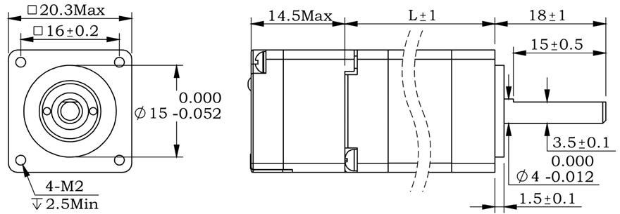
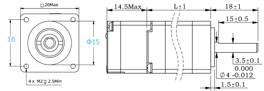
1. Pulse Type NEMA8 Integrated Stepper Motor, Terminal definition.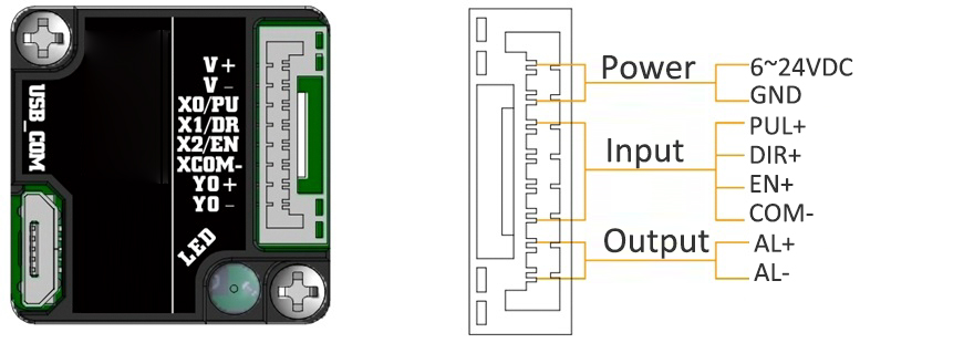
Terminal Definition
| Terminal | Name | Description | |
| 1 | V | 6 ~ 24VDC | |
| 2 | V- | GND | |
| 3 | PU | Optoelectronic isolation, differential, High level can directly receive 3.3-24VDC, with a minimum pulse width of 2us, The maximum pulse frequency is 400KHz, which can be used as a universal input port Pulse/Direction | |
| 4 | DR | ||
| 5 | EN | Optoelectronic isolation, differential, High level can directly receive 3.3-24VDC, with a minimum pulse width of 100us, The maximum pulse frequency is 10KHz, which can be used as a universal input port for Enable | |
| 6 | COM- | Input common ground | |
| 7 | AL | The default alarm output port can detect the driver alarm status and provide feedback to the main station. Other functions can be set through communication | |
| 8 | AL- | ||
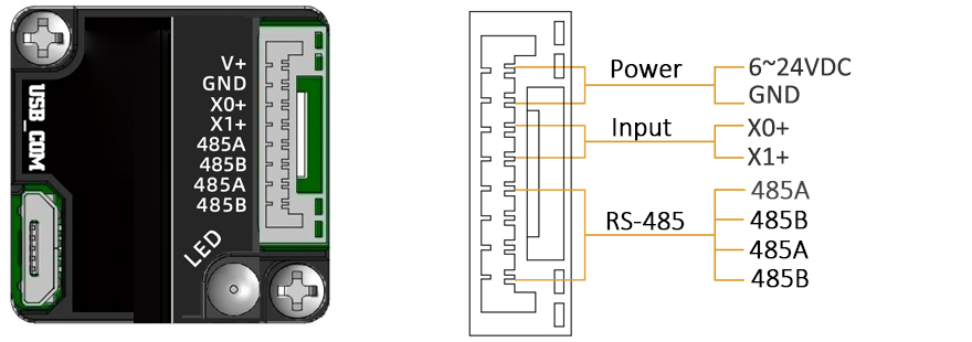
2. RS-485 Type NEMA8 Integrated Stepper Motor, Terminal definition
CRC Check Routine (C#)
UInt16 Funct_CRC16(unsigned char * puchMsg, UInt16 DataLen)
{
UInt16 i,j,tmp;
UInt16 crcdata=0xFFFF;
for(i=0;i<DataLen;i )
{
crcdata=(*puchMsg)^crcdata;
puchMsg ;
for(j=0;j<8;j )
{
tmp=crcdata&0x0001;
crcdata=crcdata>>1;
if(tmp){
crcdata=crcdata^0xA001;
}
}
}
return crcdata;
}
Software Tools for RS485 Control
Modbus Poll 
New Software in google drive ![]()
Adampower.exe
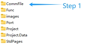
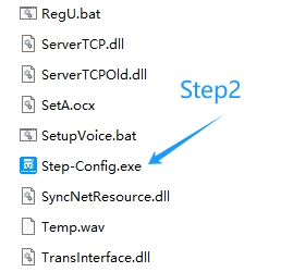
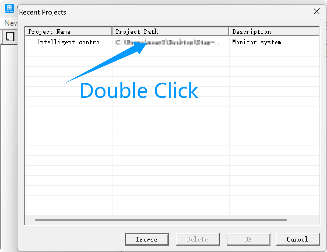
1. Extract the zip file, open CommFile folder and Click Step-Config.exe or Adampower.exe
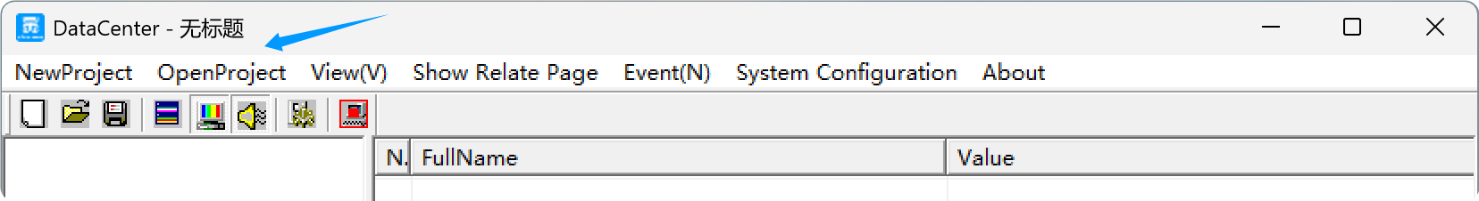
2. Open Project.
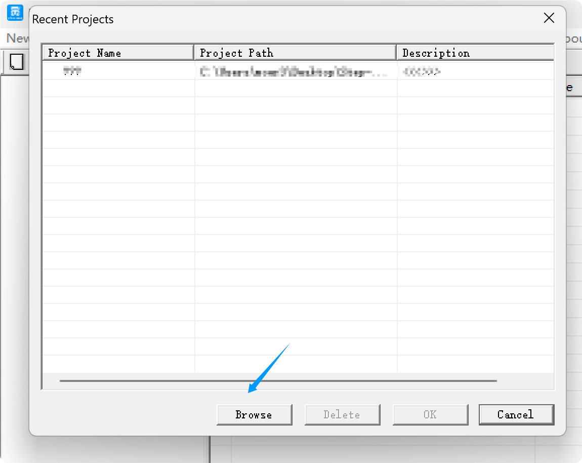
3. Click Browse
4. Select the Project.prj in the Project folder, in the same path as CommFile.
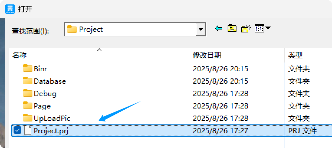
5. Double Click the Project.prj path
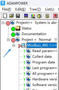
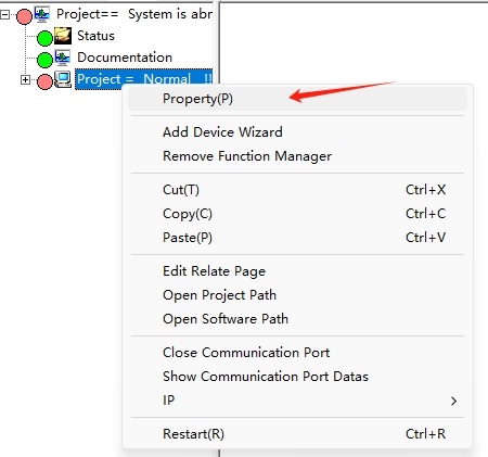
6. Right Click Modbus_485, and Click Property:
7. Click Property ComNN, Choose COM port, Baud rate and click Save and OK.
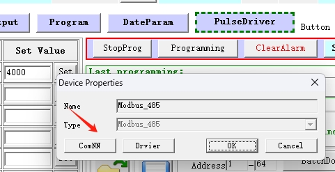
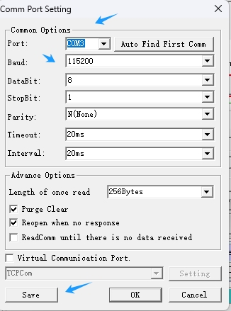
8. Start to use software control the RS485 Integrated stepper motor by below buttons:
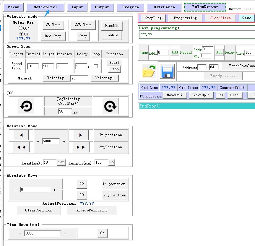
RS485 Stepper Motor Controller Manual 
Block Diagram:
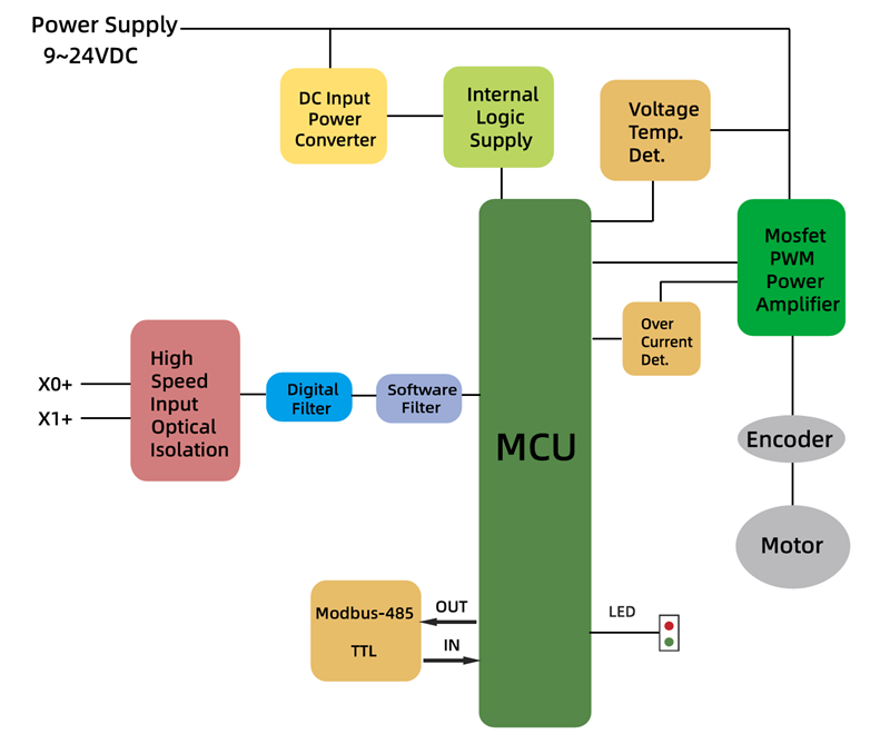
2 Input signals can directly receive 3.3-24V DC levels at high levels, Max. frequency of 400KHZ.
X0: pulse input, IO start/stop, limit, direction, universal input.
X1 pulse input, IO start/stop, limit, direction, universal input.
...
1 Output signal, maximum withstand voltage 30V, maximum input or output current 30mA
Y0 : alarm output, universal output, and factory default alarm output.
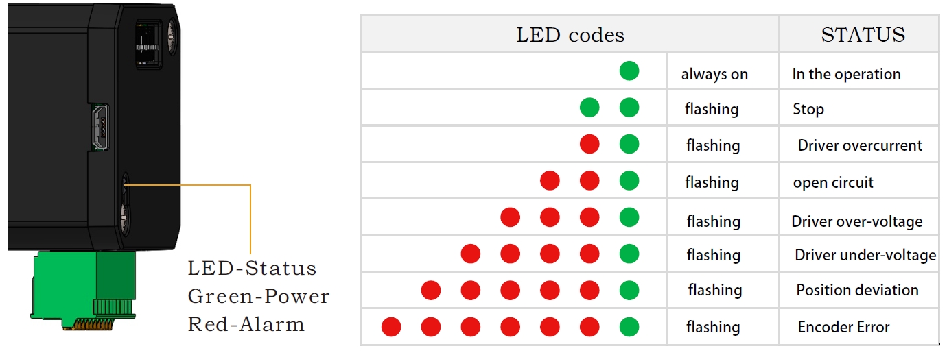
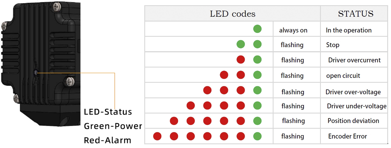
LED indicator and status:

The IG34 series integrated motor is the perfect combination of drive and stepper motor,
which perfectly integrates stepper motor and drive technology, also built in 1000 line encoder,
it can save installation space, Simultaneously saving design and production costs,
supporting RS485 and TTL communication.
| Item | Specifications |
| Stepper Motor Size | NEMA34 |
| Encoder type | 1000 line encoder |
| Working voltage | 24~80VDC, 18~60VAC |
| Driver Current | 0.5-6.5A |
| Velocity range | Up to 3000RPM |
| Control Method | RS485, Pulse& Direction, Twin-Pulse, I/O, Built-in Program |
| Torque value | 3.5 -12.5Nm |
| Nonvolatile storage | Configuration parameters are stored in FLASH inside the MCU |
| DI and DO | 2 DI, 1 DO |
| Protection | Overvoltage, undervoltage, overcurrent, open winding, position deviation |
| Digital Input (2/3) | Receive 3.3-24VDC | ||
| Digital Output(1) | Maximum withstand voltage of 30V, | ||
| Maximum input or output current 30mA | |||
Motor Parameters
| Model No. | length mm L | Shaft length mm | Shaft dia. mm | Phase current A | Resistance Ω | inductance mH | Hold torque N.m | Inertia g.cm² | Weight g |
| IG3445 | 80 | 32 | 14 | 6 | 0.5 | 3.6 | 4.5 | 1950 | 2900 |
| IG23465 | 98 | 32 | 14 | 6 | 0.63 | 4.5 | 6.5 | 2500 | 3400 |
| IG3485 | 118 | 32 | 14 | 6 | 0.5 | 4.2 | 8.5 | 2800 | 4100 |
| IG34125 | 151 | 32 | 14 | 6 | 0.63 | 4.7 | 12.5 | 4950 | 5600 |
Wiring Diagram:
1. Pulse Type Integrated Stepper Motor, Terminal Definition
Terminal Definition
| Terminal | Name | Description | |
| 1 | V | 24~60VDC | |
| 2 | V- | GND | |
| 3 | X0 (PU ) | Optoelectronic isolation, differential, High level can directly receive 3.3-24VDC, with a minimum pulse width of 2us, The maximum pulse frequency is 400KHz, which can be used as a universal input port for Pulse/Direction | |
| 4 | X0-(PU-) | ||
| 5 | X1 (DR ) | ||
| 6 | X1-(DR-) | ||
| 7 | X2(EN ) | Optoelectronic isolation, differential, High level can directly receive 3.3-24VDC, with a minimum pulse width of 100us, The maximum pulse frequency is 10KHz, which can be used as a universal input port for Enable | |
| 8 | X2(EN-) | ||
| 9 | Y0 (AL ) | The default alarm output port can detect the driver alarm status and provide feedback to the main station. Other functions can be set through communication | |
| 10 | Y0-(AL-) | ||
| 11 | Y1(EX ) | The default In-place output , Other functions can be set through communication | |
| 12 | Y1(EX-) | ||
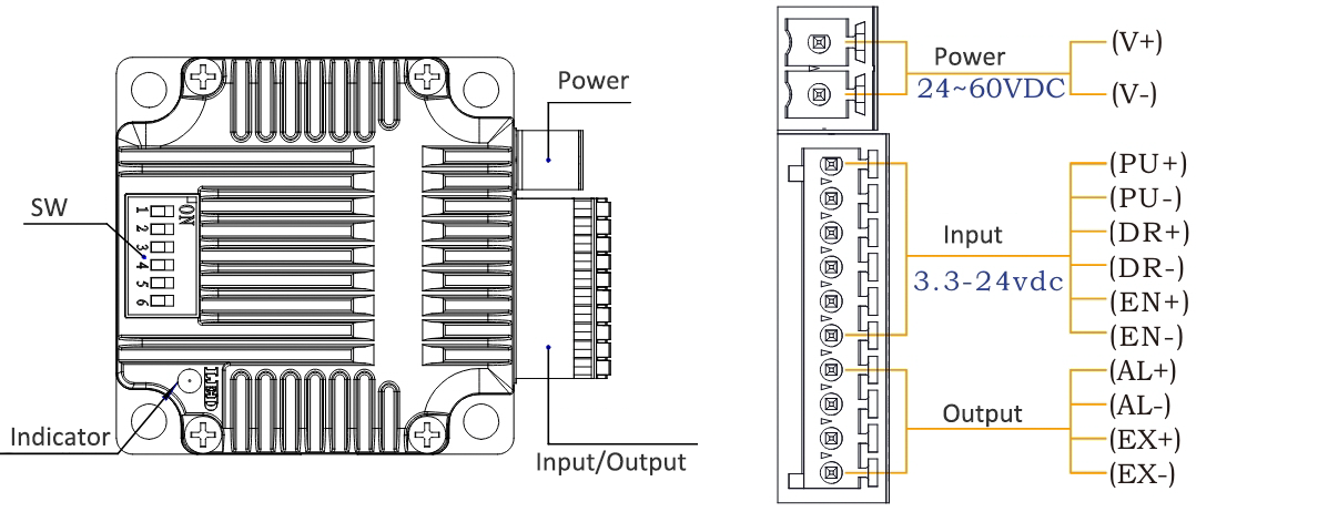
Set Micro-step by SW1, SW2, SW3 and SW4: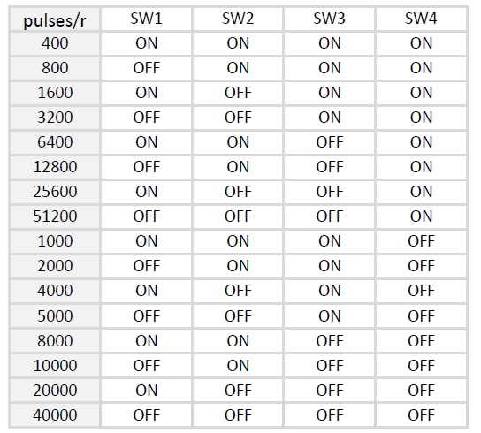
SW5=OFF: Pulse & Direction; SW=ON: Twin Pulse mode.
SW6=OFF: CW direction; SW6=ON: CCW direction.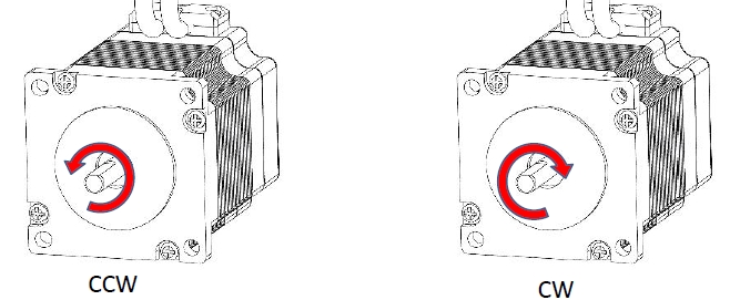
2. RS485 Type Integrated Stepper Motor, Terminal Definition
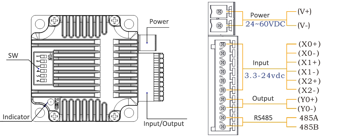
Terminal Definition
| Terminal | Name | Description | |
| 1 | V | 24~60VDC | |
| 2 | V- | GND | |
| 3 | X0 (PU ) | Optoelectronic isolation, differential, High level can directly receive 3.3-24VDC, with a minimum pulse width of 2us, The maximum pulse frequency is 400KHz, which can be used as a universal input port for Pulse/Direction | |
| 4 | X0-(PU-) | ||
| 5 | X1 (DR ) | ||
| 6 | X1-(DR-) | ||
| 7 | X2 (EN ) | ||
| 8 | X2-(EN-) | ||
| 9 | Y0 (AL ) | The default alarm output port can detect the driver alarm status and provide feedback to the main station. Other functions can be set through communication | |
| 10 | Y0-(AL-) | ||
| 11 | 485A | RS485 Communication port, default baud rate is 115200 | |
| 12 | 485B | ||
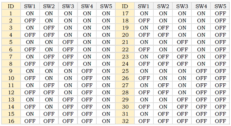
Set Device ID for RS485 integrated Stepper Motor by SW1 ~ SW5:
SW6 is used to set the terminal resistance; OFF=0 ohms; ON=120 ohms
CRC Check Routine (C#)
UInt16 Funct_CRC16(unsigned char * puchMsg, UInt16 DataLen)
{
UInt16 i,j,tmp;
UInt16 crcdata=0xFFFF;
for(i=0;i<DataLen;i )
{
crcdata=(*puchMsg)^crcdata;
puchMsg ;
for(j=0;j<8;j )
{
tmp=crcdata&0x0001;
crcdata=crcdata>>1;
if(tmp){
crcdata=crcdata^0xA001;
}
}
}
return crcdata;
}
Software Tools for RS485 Control
Modbus Poll
New Software in google drive ![]()
Step-Config
1. Extract the zip file, open CommFile folder and Click Step-Config.exe or Adampower.exe
2. Open Project.
3. Click Browse
4. Select the Project.prj in the Project folder, in the same path as CommFile.
5. Double Click the Project.prj path
6. Right Click Modbus_485, and Click Property:
7. Click Property ComNN, Choose COM port, Baud rate and click Save and OK.
8. Start to use software control the RS485 Integrated stepper motor by below buttons:
RS485 Stepper Motor Controller Manual
Block Diagram: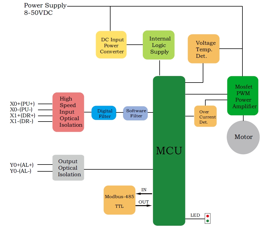
2 Input signals can directly receive 3.3-24V DC levels at high levels, Max. frequency of 400KHZ.
X0: pulse input, IO start/stop, limit, direction, universal input.
X1 pulse input, IO start/stop, limit, direction, universal input.
...
1 Output signal, maximum withstand voltage 30V, maximum input or output current 30mA
Y0 : alarm output, universal output, and factory default alarm output.
LED indicator and status:

The IG23 series integrated motor is the perfect combination of drive and stepper motor,
which perfectly integrates stepper motor and drive technology, also built in 1000 line encoder,
it can save installation space, Simultaneously saving design and production costs,
supporting RS485 and TTL communication.
| Item | Specifications |
| Stepper Motor Size | NEMA23 |
| Encoder type | 1000 line encoder |
| Working voltage | 8-60VDC, Recommend DC36V |
| Driver Current | 0.5-5A |
| Velocity range | Up to 3000RPM |
| Control Method | RS485, Pulse& Direction, Twin-Pulse, I/O, Built-in Program |
| Torque value | 0.8 - 2.2Nm |
| Nonvolatile storage | Configuration parameters are stored in FLASH inside the MCU |
| DI and DO | 2 DI, 1 DO |
| Protection | Overvoltage, undervoltage, overcurrent, open winding, position deviation |
| Digital Input (2/3) | Receive 3.3-24VDC | ||
| Digital Output(1) | Maximum withstand voltage of 30V, | ||
| Maximum input or output current 30mA | |||
Motor Parameters
| Model No. | length mm L | Shaft length mm | Shaft dia. mm | Phase current A | Resistance Ω | inductance mH | Hold torque N.m | Inertia g.cm² | Weight g |
| IG2312 | 68 | 21 | 8 | 4 | 0.5 | 1.8 | 1.2 | 280 | 800 |
| IG2320 | 85 | 21 | 8 | 5 | 0.4 | 2.0 | 2.0 | 480 | 1100 |
Wiring Diagram:
1. Pulse Type Integrated Stepper Motor, Terminal Definition
Terminal Definition
| Terminal | Name | Description | |
| 1 | V | 24~60VDC | |
| 2 | V- | GND | |
| 3 | X0 (PU ) | Optoelectronic isolation, differential, High level can directly receive 3.3-24VDC, with a minimum pulse width of 2us, The maximum pulse frequency is 400KHz, which can be used as a universal input port for Pulse/Direction | |
| 4 | X0-(PU-) | ||
| 5 | X1 (DR ) | ||
| 6 | X1-(DR-) | ||
| 7 | X2(EN ) | Optoelectronic isolation, differential, High level can directly receive 3.3-24VDC, with a minimum pulse width of 100us, The maximum pulse frequency is 10KHz, which can be used as a universal input port for Enable | |
| 8 | X2(EN-) | ||
| 9 | Y0 (AL ) | The default alarm output port can detect the driver alarm status and provide feedback to the main station. Other functions can be set through communication | |
| 10 | Y0-(AL-) | ||
| 11 | Y1(EX ) | The default In-place output , Other functions can be set through communication | |
| 12 | Y1(EX-) | ||
Set Micro-step by SW1, SW2, SW3 and SW4:
SW5=OFF: Pulse & Direction; SW=ON: Twin Pulse mode.
SW6=OFF: CW direction; SW6=ON: CCW direction.
2. RS485 Type Integrated Stepper Motor, Terminal Definition
Terminal Definition
| Terminal | Name | Description | |
| 1 | V | 24~60VDC | |
| 2 | V- | GND | |
| 3 | X0 (PU ) | Optoelectronic isolation, differential, High level can directly receive 3.3-24VDC, with a minimum pulse width of 2us, The maximum pulse frequency is 400KHz, which can be used as a universal input port for Pulse/Direction/Enable | |
| 4 | X0-(PU-) | ||
| 5 | X1 (DR ) | ||
| 6 | X1-(DR-) | ||
| 7 | X2 (EN ) | ||
| 8 | X2-(EN-) | ||
| 9 | Y0 (AL ) | The default alarm output port can detect the driver alarm status and provide feedback to the main station. Other functions can be set through communication | |
| 10 | Y0-(AL-) | ||
| 11 | 485A | RS485 Communication port, default baud rate is 115200 | |
| 12 | 485B | ||
Set Device ID for RS485 integrated Stepper Motor by SW1 ~ SW5:
SW6 is used to set the terminal resistance; OFF=0 ohms; ON=120 ohms
CRC Check Routine (C#)
UInt16 Funct_CRC16(unsigned char * puchMsg, UInt16 DataLen)
{
UInt16 i,j,tmp;
UInt16 crcdata=0xFFFF;
for(i=0;i<DataLen;i )
{
crcdata=(*puchMsg)^crcdata;
puchMsg ;
for(j=0;j<8;j )
{
tmp=crcdata&0x0001;
crcdata=crcdata>>1;
if(tmp){
crcdata=crcdata^0xA001;
}
}
}
return crcdata;
}
Software Tools for RS485 Control
Modbus Poll
Software in google drive ![]()
Adampower
1. Extract the zip file, open CommFile folder and Click Step-Config.exe or Adampower.exe
2. Open Project.
3. Click Browse
4. Select the Project.prj in the Project folder, in the same path as CommFile.
5. Double Click the Project.prj path
6. Right Click Modbus_485, and Click Property:
7. Click Property ComNN, Choose COM port, Baud rate and click Save and OK.
8. Start to use software control the RS485 Integrated stepper motor by below buttons:
RS485 Stepper Motor Controller Manual
Block Diagram:
2 Input signals can directly receive 3.3-24V DC levels at high levels, Max. frequency of 400KHZ.
X0: pulse input, IO start/stop, limit, direction, universal input.
X1 pulse input, IO start/stop, limit, direction, universal input.
...
1 Output signal, maximum withstand voltage 30V, maximum input or output current 30mA
Y0 : alarm output, universal output, and factory default alarm output.
LED indicator and status:

The IG24 series integrated motor is the perfect combination of drive and stepper motor,
which perfectly integrates stepper motor and drive technology, also built in 1000 line encoder,
it can save installation space, Simultaneously saving design and production costs,
supporting RS485 and TTL communication.
| Item | Specifications |
| Stepper Motor Size | NEMA24 |
| Encoder type | 1000 line encoder |
| Working voltage | 24-60VDC |
| Driver Current | 0.5-5A |
| Velocity range | Up to 3000RPM |
| Control Method | RS485, Pulse& Direction, Twin-Pulse, I/O, Built-in Program |
| Torque value | 1.6 - 3.5Nm |
| Nonvolatile storage | Configuration parameters are stored in FLASH inside the MCU |
| DI and DO | 2 DI, 1 DO |
| Protection | Overvoltage, undervoltage, overcurrent, open winding, position deviation |
| Digital Input (2/3) | Receive 3.3-24VDC | ||
| Digital Output(1) | Maximum withstand voltage of 30V, | ||
| Maximum input or output current 30mA | |||
Motor Parameters
| Model No. | length mm L | Shaft length mm | Shaft dia. mm | Phase current A | Resistance Ω | inductance mH | Hold torque N.m | Inertia g.cm² | Weight g |
| IG2422 | 68 | 21 | 8 | 5 | 0.33 | 1.05 | 2.2 | 490 | 1300 |
| IG2430 | 85 | 21 | 8 | 5 | 0.43 | 2.0 | 3.0 | 690 | 1500 |
Wiring Diagram:
1. Pulse Type Integrated Stepper Motor, Terminal Definition
Terminal Definition
| Terminal | Name | Description | |
| 1 | V | 24~60VDC | |
| 2 | V- | GND | |
| 3 | X0 (PU ) | Optoelectronic isolation, differential, High level can directly receive 3.3-24VDC, with a minimum pulse width of 2us, The maximum pulse frequency is 400KHz, which can be used as a universal input port for Pulse/Direction | |
| 4 | X0-(PU-) | ||
| 5 | X1 (DR ) | ||
| 6 | X1-(DR-) | ||
| 7 | X2(EN ) | Optoelectronic isolation, differential, High level can directly receive 3.3-24VDC, with a minimum pulse width of 100us, The maximum pulse frequency is 10KHz, which can be used as a universal input port for Enable | |
| 8 | X2(EN-) | ||
| 9 | Y0 (AL ) | The default alarm output port can detect the driver alarm status and provide feedback to the main station. Other functions can be set through communication | |
| 10 | Y0-(AL-) | ||
| 11 | Y1(EX ) | The default In-place output , Other functions can be set through communication | |
| 12 | Y1(EX-) | ||
Set Micro-step by SW1, SW2, SW3 and SW4:
SW5=OFF: Pulse & Direction; SW=ON: Twin Pulse mode.
SW6=OFF: CW direction; SW6=ON: CCW direction.
2. RS485 Type Integrated Stepper Motor, Terminal Definition
Terminal Definition
| Terminal | Name | Description | |
| 1 | V | 24~60VDC | |
| 2 | V- | GND | |
| 3 | X0 (PU ) | Optoelectronic isolation, differential, High level can directly receive 3.3-24VDC, with a minimum pulse width of 2us, The maximum pulse frequency is 400KHz, which can be used as a universal input port for Pulse/Direction/Enable | |
| 4 | X0-(PU-) | ||
| 5 | X1 (DR ) | ||
| 6 | X1-(DR-) | ||
| 7 | X2 (EN ) | ||
| 8 | X2-(EN-) | ||
| 9 | Y0 (AL ) | The default alarm output port can detect the driver alarm status and provide feedback to the main station. Other functions can be set through communication | |
| 10 | Y0-(AL-) | ||
| 11 | 485A | RS485 Communication port, default baud rate is 115200 | |
| 12 | 485B | ||
Set Device ID for RS485 integrated Stepper Motor by SW1 ~ SW5:
SW6 is used to set the terminal resistance; OFF=0 ohms; ON=120 ohms
CRC Check Routine (C#)
UInt16 Funct_CRC16(unsigned char * puchMsg, UInt16 DataLen)
{
UInt16 i,j,tmp;
UInt16 crcdata=0xFFFF;
for(i=0;i<DataLen;i )
{
crcdata=(*puchMsg)^crcdata;
puchMsg ;
for(j=0;j<8;j )
{
tmp=crcdata&0x0001;
crcdata=crcdata>>1;
if(tmp){
crcdata=crcdata^0xA001;
}
}
}
return crcdata;
}
Software Tools for RS485 Control
Modbus Poll
Software in google drive ![]()
Step-Config
1. Extract the zip file, open CommFile folder and Click Step-Config.exe or Adampower.exe
2. Open Project.
3. Click Browse
4. Select the Project.prj in the Project folder, in the same path as CommFile.
5. Double Click the Project.prj path
6. Right Click Modbus_485, and Click Property:
7. Click Property ComNN, Choose COM port, Baud rate and click Save and OK.
8. Start to use software control the RS485 Integrated stepper motor by below buttons:
RS485 Stepper Motor Controller Manual
Block Diagram:
2 Input signals can directly receive 3.3-24V DC levels at high levels, Max. frequency of 400KHZ.
X0: pulse input, IO start/stop, limit, direction, universal input.
X1 pulse input, IO start/stop, limit, direction, universal input.
...
1 Output signal, maximum withstand voltage 30V, maximum input or output current 30mA
Y0 : alarm output, universal output, and factory default alarm output.
LED indicator and status:

The IG17 series integrated motor is the perfect combination of drive and stepper motor,
which perfectly integrates stepper motor and drive technology, also built in 1000 line encoder,
it can save installation space, Simultaneously saving design and production costs,
supporting RS485 and TTL communication.
| Item | Specifications |
| Stepper Motor Size | NEMA17 |
| Encoder type | 1000 line encoder |
| Working voltage | 8-50VDC, Recommend DC36V |
| Driver Current | 0.2-3.2A |
| Velocity range | Up to 3000RPM |
| Control Method | RS485, Pulse& Direction, Twin-Pulse, I/O, Built-in Program |
| Torque value | 0.2 - 6Nm |
| Nonvolatile storage | Configuration parameters are stored in FLASH inside the MCU |
| DI and DO | 2 DI, 1 DO |
| Protection | Overvoltage, undervoltage, overcurrent, open winding, position deviation |
| Digital Input (2/3) | Receive 3.3-24VDC | ||
| Digital Output(1) | Maximum withstand voltage of 30V, | ||
| Maximum input or output current 30mA | |||
Motor Parameters
| Model No. | length mm L | Shaft length mm | Shaft dia. mm | Phase current A | Resistance Ω | inductance mH | Hold torque N.m | Inertia g.cm² | Weight g |
| IG1704 | 40 | 21 | 8 | 2.0 | 2 | 4.2 | 0.4 | 57 | 380 |
| IG1705 | 48 | 21 | 8 | 2.0 | 1.3 | 2.9 | 0.5 | 82 | 460 |
| IG1706 | 60 | 21 | 8 | 2.5 | 1.3 | 3.2 | 0.6 | 116 | 700 |
Wiring Diagram:
1. Pulse Type Integrated Stepper Motor, Terminal Definition
Terminal Definition
| Terminal | Name | Description | |
| 1 | V | 8-48VDC | |
| 2 | V- | GND | |
| 3 | X0 (PU ) | Optoelectronic isolation, differential, High level can directly receive 3.3-24VDC, with a minimum pulse width of 2us, The maximum pulse frequency is 400KHz, which can be used as a universal input port for Pulse/Direction | |
| 4 | X0-(PU-) | ||
| 5 | X1 (DR ) | ||
| 6 | X1-(DR-) | ||
| 7 | X2(EN ) | Optoelectronic isolation, differential, High level can directly receive 3.3-24VDC, with a minimum pulse width of 100us, The maximum pulse frequency is 10KHz, which can be used as a universal input port for Enable | |
| 8 | X2(EN-) | ||
| 9 | Y0 (AL ) | The default alarm output port can detect the driver alarm status and provide feedback to the main station. Other functions can be set through communication | |
| 10 | Y0-(AL-) | ||
Set Micro-step by SW1, SW2, SW3 and SW4:
SW5=OFF: Pulse & Direction; SW=ON: Twin Pulse mode.
SW6=OFF: CW direction; SW6=ON: CCW direction.
2. RS485 Type Integrated Stepper Motor, Terminal Definition
Terminal Definition
| Terminal | Name | Description | |
| 1 | V | 8-48VDC | |
| 2 | V- | GND | |
| 3 | X0 (PU ) | Optoelectronic isolation, differential, High level can directly receive 3.3-24VDC, with a minimum pulse width of 2us, The maximum pulse frequency is 400KHz, which can be used as a universal input port or a high-speed pulse input port | |
| 4 | X0-(PU-) | ||
| 5 | X1 (DR ) | ||
| 6 | X1-(DR-) | ||
| 7 | 485A(EN ) | RS485 Communication port, default baud rate is 115200, | |
| 8 | 485B(EN-) | ||
| 9 | Y0 (AL ) | The default alarm output port can detect the driver alarm status and provide feedback to the main station. Other functions can be set through communication | |
| 10 | Y0-(AL-) | ||
Set Device ID for RS485 integrated Stepper Motor by SW1 ~ SW5:
SW6 is used to set the terminal resistance; OFF=0 ohms; ON=120 ohms
CRC Check Routine (C#)
UInt16 Funct_CRC16(unsigned char * puchMsg, UInt16 DataLen)
{
UInt16 i,j,tmp;
UInt16 crcdata=0xFFFF;
for(i=0;i<DataLen;i )
{
crcdata=(*puchMsg)^crcdata;
puchMsg ;
for(j=0;j<8;j )
{
tmp=crcdata&0x0001;
crcdata=crcdata>>1;
if(tmp){
crcdata=crcdata^0xA001;
}
}
}
return crcdata;
}
Software Tools for RS485 Control
Modbus Poll
Software in google drive ![]()
Step-Config
1. Extract the zip file, open CommFile folder and Click Step-Config.exe or Adampower.exe
2. Open Project.
3. Click Browse
4. Select the Project.prj in the Project folder, in the same path as CommFile.
5. Double Click the Project.prj path
6. Right Click Modbus_485, and Click Property:
7. Click Property ComNN, Choose COM port, Baud rate and click Save and OK.
8. Start to use software control the RS485 Integrated stepper motor by below buttons:
RS485 Stepper Motor Controller Manual
Block Diagram:
2 Input signals can directly receive 3.3-24V DC levels at high levels, Max. frequency of 400KHZ.
X0: pulse input, IO start/stop, limit, direction, universal input.
X1 pulse input, IO start/stop, limit, direction, universal input.
...
1 Output signal, maximum withstand voltage 30V, maximum input or output current 30mA
Y0 : alarm output, universal output, and factory default alarm output.
LED indicator and status:

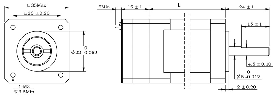
The IG14 series integrated motor is the perfect combination of drive and stepper motor,
which perfectly integrates stepper motor and drive technology, also built in 1000 line encoder,
it can save installation space, Simultaneously saving design and production costs,
supporting RS485 and TTL communication.
| Item | Specifications |
| Stepper Motor Size | NEMA14 |
| Encoder type | 1000 line encoder |
| Working voltage | 8 ~ 36VDC |
| Driver Current | 0.2-2.0A |
| Velocity range | Up to 3000RPM |
| Control Method | RS485, Pulse& Direction, Twin-Pulse, I/O, Built-in Program |
| Torque value | 0.2 - 0.4Nm |
| Nonvolatile storage | Configuration parameters are stored in FLASH inside the MCU |
| DI and DO | 2/3 DI, 1 DO |
| Protection | Overvoltage, undervoltage, overcurrent, open winding, position deviation |
| Digital Input (2/3) | Receive 3.3-24VDC | ||
| Digital Output(1) | Maximum withstand voltage of 30V, | ||
| Maximum input or output current 30mA | |||
Motor Parameters
Pulse type NEMA14 integrated Stepper Motor:
| Model No. | length mm L | Shaft length mm | Shaft dia. mm | Phase current A | Resistance Ω | inductance mH | Hold torque N.m | Inertia g.cm² | Weight g |
| IG1418 | 32 | 24 | 5 | 1.5 | 1.5 | 1.6 | 0.18 | 15 | 200 |
| IG1425 | 37 | 24 | 5 | 1.5 | 1.5 | 2.0 | 0.25 | 26 | 250 |
| IG1440 | 50 | 24 | 5 | 1.8 | 1.1 | 2.5 | 0.40 | 38 | 350 |
RS485 type NEMA14 integrated Stepper Motor:
| Model No. | length mm L | Shaft length mm | Shaft dia. mm | Phase current A | Resistance Ω | inductance mH | Hold torque N.m | Inertia g.cm² | Weight g |
| IG1412 | 26 | 24 | 5 | 1.0 | 1.5 | 1.9 | 0.12 | 8 | 230 |
| IG1420 | 34 | 24 | 5 | 1.5 | 2.1 | 2.1 | 0.20 | 14 | 290 |
| IG1425 | 40 | 24 | 5 | 1.5 | 2.5 | 2.8 | 0.25 | 20 | 340 |
| IG1435 | 53 | 24 | 5 | 1.8 | 2.9 | 4.8 | 0.35 | 31 | 440 |
Wiring Diagram:
1. Pulse Type Integrated Stepper Motor, Terminal Definition

Terminal Definition
| Terminal | Name | Description | |
| 1 | V | 8-48VDC | |
| 2 | V- | GND | |
| 3 | X0 (PU ) | Optoelectronic isolation, differential, High level can directly receive 3.3-24VDC, with a minimum pulse width of 2us, The maximum pulse frequency is 400KHz, which can be used as a universal input port for Pulse/Direction | |
| 4 | X0-(PU-) | ||
| 5 | X1 (DR ) | ||
| 6 | X1-(DR-) | ||
| 7 | X2(EN ) | Optoelectronic isolation, differential, High level can directly receive 3.3-24VDC, with a minimum pulse width of 100us, The maximum pulse frequency is 10KHz, which can be used as a universal input port for Enable | |
| 8 | X2(EN-) | ||
| 9 | Y0 (AL ) | The default alarm output port can detect the driver alarm status and provide feedback to the main station. Other functions can be set through communication | |
| 10 | Y0-(AL-) | ||
| 11 | Y1 | Default function is in-place output | |
| 12 | Y1- | ||
2. RS485 Type Integrated Stepper Motor, Terminal Definition
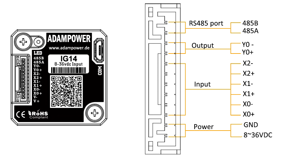
Terminal Definition
| Terminal | Name | Description | |
| 1 | V | 8-48VDC | |
| 2 | V- | GND | |
| 3 | X0 (PU ) | Optoelectronic isolation, differential, High level can directly receive 3.3-24VDC, with a minimum pulse width of 2us, The maximum pulse frequency is 400KHz, which can be used as a universal input port or a high-speed pulse input port | |
| 4 | X0-(PU-) | ||
| 5 | X1 (DR ) | ||
| 6 | X1-(DR-) | ||
| 7 | X2 | ||
| 8 | X2- | ||
| 9 | Y0 (AL ) | The default alarm output port can detect the driver alarm status and provide feedback to the main station. Other functions can be set through communication | |
| 10 | Y0-(AL-) | ||
| 11 | 485A | RS485 Communication port, default baud rate is 115200, | |
| 12 | 485B | ||
CRC Check Routine (C#)
UInt16 Funct_CRC16(unsigned char * puchMsg, UInt16 DataLen)
{
UInt16 i,j,tmp;
UInt16 crcdata=0xFFFF;
for(i=0;i<DataLen;i )
{
crcdata=(*puchMsg)^crcdata;
puchMsg ;
for(j=0;j<8;j )
{
tmp=crcdata&0x0001;
crcdata=crcdata>>1;
if(tmp){
crcdata=crcdata^0xA001;
}
}
}
return crcdata;
}
Software Tools for RS485 Control
Modbus Poll
Software in google drive ![]()
Step-Config
1. Extract the zip file, open CommFile folder and Click Step-Config.exe or Adampower.exe
2. Open Project.
3. Click Browse
4. Select the Project.prj in the Project folder, in the same path as CommFile.
5. Double Click the Project.prj path
6. Right Click Modbus_485, and Click Property:
7. Click Property ComNN, Choose COM port, Baud rate and click Save and OK.
8. Start to use software control the RS485 Integrated stepper motor by below buttons:
RS485 Stepper Motor Controller Manual
Block Diagram:
2 Input signals can directly receive 3.3-24V DC levels at high levels, Max. frequency of 400KHZ.
X0: pulse input, IO start/stop, limit, direction, universal input.
X1 pulse input, IO start/stop, limit, direction, universal input.
...
1 Output signal, maximum withstand voltage 30V, maximum input or output current 30mA
Y0 : alarm output, universal output, and factory default alarm output.
LED indicator and status:

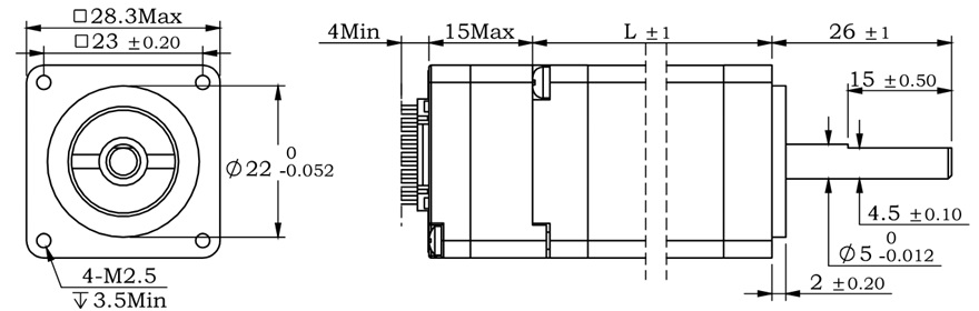
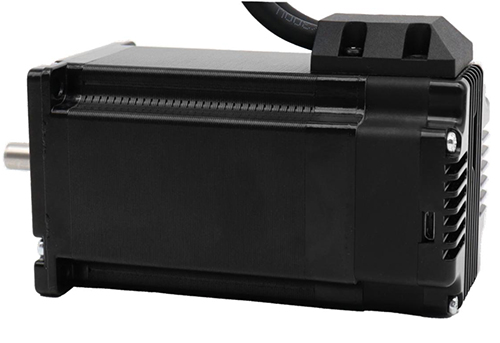
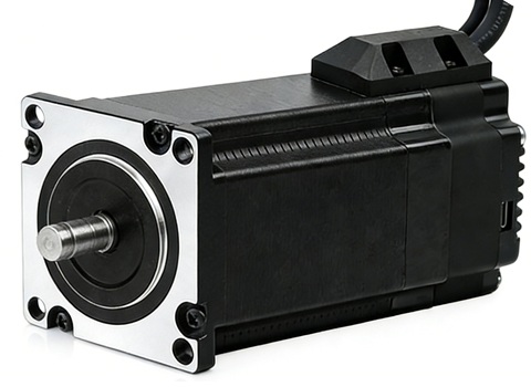
The IG11 series integrated motor is the perfect combination of drive and stepper motor,
which perfectly integrates stepper motor and drive technology, also built in 1000 line encoder,
it can save installation space, Simultaneously saving design and production costs,
supporting RS485 and TTL communication.
| Item | Specifications |
| Stepper Motor Size | NEMA11 |
| Encoder type | 1000 line encoder |
| Working voltage | 8~36VDC |
| Driver Current | 0.2-2.0A |
| Velocity range | Up to 3000RPM |
| Control Method | RS485, Pulse& Direction, Twin-Pulse, I/O, Built-in Program |
| Torque value | 0.08 - 0.24Nm |
| Nonvolatile storage | Configuration parameters are stored in FLASH inside the MCU |
| DI and DO | 2/3 DI, 1 DO |
| Protection | Overvoltage, undervoltage, overcurrent, open winding, position deviation |
| Digital Input (2/3) | Receive 3.3-24VDC | ||
| Digital Output(1) | Maximum withstand voltage of 30V, | ||
| Maximum input or output current 30mA | |||
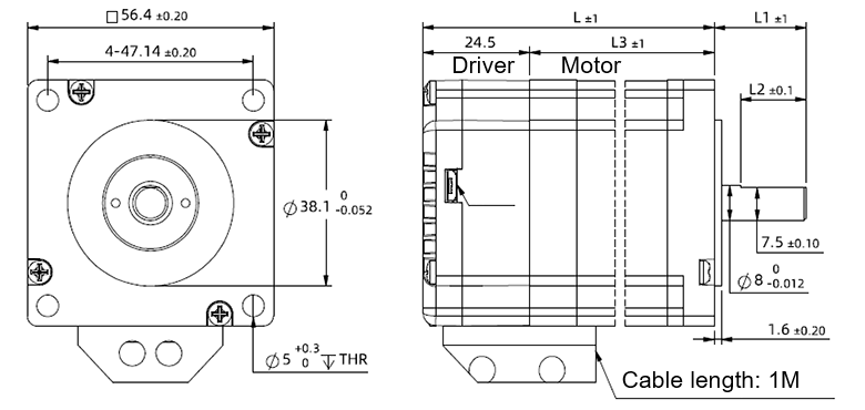
Motor Parameters
NEMA11 integrated Stepper Motor:
| Model No. | length mm L | Shaft length mm | Shaft dia. mm | Phase current A | Resistance Ω | inductance mH | Hold torque N.m | Inertia g.cm² | Weight g |
| IG11008 | 31 | 26 | 5 | 1.0 | 1.5 | 1.1 | 0.08 | 9 | 115 |
| IG11018 | 52 | 26 | 5 | 1.3 | 2.4 | 2.3 | 0.18 | 18 | 205 |
| IG11024 | 63 | 26 | 5 | 1.5 | 1.8 | 2.1 | 0.24 | 30 | 268 |
Wiring Diagram:
1. Pulse Type Integrated Stepper Motor, Terminal Definition
Terminal Definition
| Terminal | Name | Description | |
| 1 | V | 8-36VDC | |
| 2 | V- | GND | |
| 3 | X0 (PU ) | Optoelectronic isolation, differential, High level can directly receive 3.3-24VDC, with a minimum pulse width of 2us, The maximum pulse frequency is 400KHz, which can be used as a universal input port for Pulse/Direction | |
| 4 | X0-(PU-) | ||
| 5 | X1 (DR ) | ||
| 6 | X1-(DR-) | ||
| 7 | X2(EN ) | Optoelectronic isolation, differential, High level can directly receive 3.3-24VDC, with a minimum pulse width of 100us, The maximum pulse frequency is 10KHz, which can be used as a universal input port for Enable | |
| 8 | X2(EN-) | ||
| 9 | Y0 (AL ) | The default alarm output port can detect the driver alarm status and provide feedback to the main station. Other functions can be set through communication | |
| 10 | Y0-(AL-) | ||
| 11 | Y1 | Default function is in-place output | |
| 12 | Y1- | ||
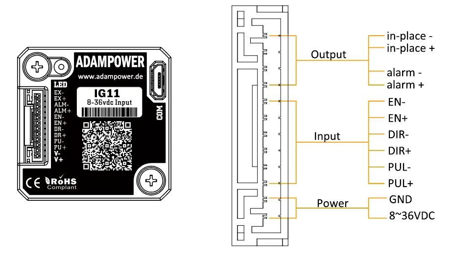
2. RS485 Type Integrated Stepper Motor, Terminal Definition
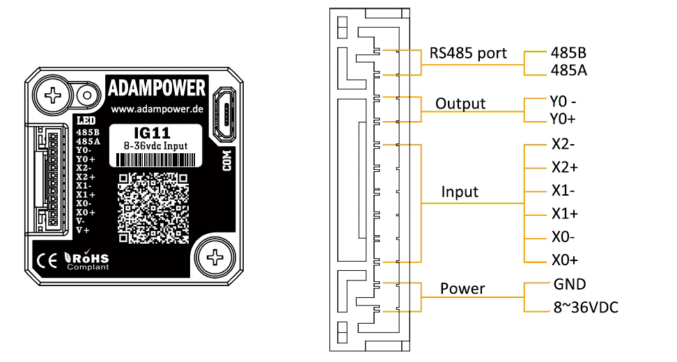
Terminal Definition
| Terminal | Name | Description | |
| 1 | V | 8-36VDC | |
| 2 | V- | GND | |
| 3 | X0 (PU ) | Optoelectronic isolation, differential, High level can directly receive 3.3-24VDC, with a minimum pulse width of 2us, The maximum pulse frequency is 400KHz, which can be used as a universal input port or a high-speed pulse input port | |
| 4 | X0-(PU-) | ||
| 5 | X1 (DR ) | ||
| 6 | X1-(DR-) | ||
| 7 | X2(EN ) | ||
| 8 | X2-(EN-) | ||
| 9 | Y0 (AL ) | The default alarm output port can detect the driver alarm status and provide feedback to the main station. Other functions can be set through communication | |
| 10 | Y0-(AL-) | ||
| 11 | 485A | RS485 Communication port, default baud rate is 115200, | |
| 12 | 485B | ||
CRC Check Routine (C#)
UInt16 Funct_CRC16(unsigned char * puchMsg, UInt16 DataLen)
{
UInt16 i,j,tmp;
UInt16 crcdata=0xFFFF;
for(i=0;i<DataLen;i )
{
crcdata=(*puchMsg)^crcdata;
puchMsg ;
for(j=0;j<8;j )
{
tmp=crcdata&0x0001;
crcdata=crcdata>>1;
if(tmp){
crcdata=crcdata^0xA001;
}
}
}
return crcdata;
}
Software Tools for RS485 Control
Modbus Poll
Software in google drive ![]()
Step-Config
1. Extract the zip file, open CommFile folder and Click Step-Config.exe or Adampower.exe
2. Open Project.
3. Click Browse
4. Select the Project.prj in the Project folder, in the same path as CommFile.
5. Double Click the Project.prj path
6. Right Click Modbus_485, and Click Property:
7. Click Property ComNN, Choose COM port, Baud rate and click Save and OK.
8. Start to use software control the RS485 Integrated stepper motor by below buttons:
RS485 Stepper Motor Controller Manual
Block Diagram:
2 Input signals can directly receive 3.3-24V DC levels at high levels, Max. frequency of 400KHZ.
X0: pulse input, IO start/stop, limit, direction, universal input.
X1 pulse input, IO start/stop, limit, direction, universal input.
...
1 Output signal, maximum withstand voltage 30V, maximum input or output current 30mA
Y0 : alarm output, universal output, and factory default alarm output.
LED indicator and status:

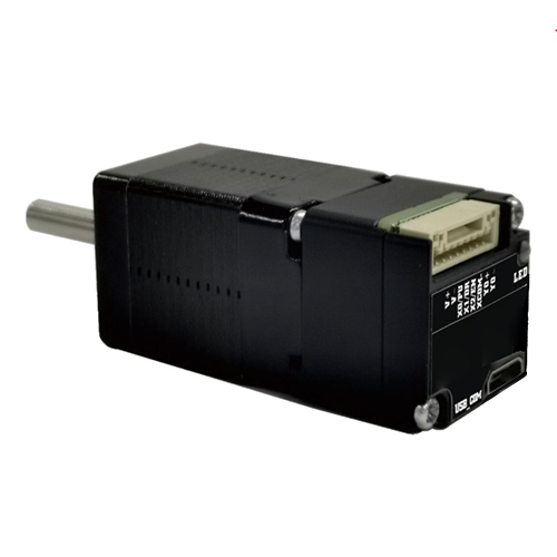
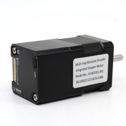
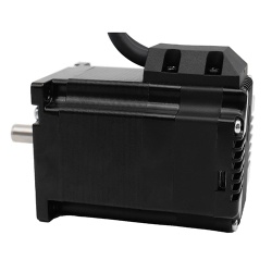
The IM23ET Series Integrated Motors represent a perfect integration of stepper drivers and stepper motors, combining the technologies of both in a single unit.
They are fully compatible with 1599-revolution mechanical absolute encoders, which not only save installation space but also streamline wiring connections.
By reducing your design and production costs, they stand as the premier choice for your stepper system solutions.
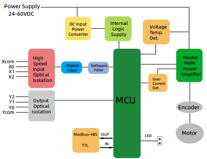
Frame Size: NEMA23
Holding Torque: 0.8–3.0 N·m
Supply Voltage: 24–60 VDC
Supported Protocols: Modbus/RTU, RS485
Built-in Programmable Multi-Turn Feedback: 1599 revolutions; supports user-defined home position with memory, no sensor required
Software Limit Function Supported: More reliable than mechanical limit switches
Closed-Loop Control: 4096-line (16384 counts) encoder feedback
Torque Modes Supported: Homing on collision, constant torque, object gripping
Input Compatibility: 5–24 VDC; Output: Open-collector (OC) output, withstanding voltage up to 30 VDC
Comprehensive Protection Features: Over-voltage, under-voltage, over-current, winding open-circuit, and position deviation protection
Non-Volatile Memory: Configuration parameters stored in the on-chip FLASH of the MCU
Wide Filter Frequency Range: 50 kHz–5 MHz adjustable, factory default at 300 kHz
User-friendly PC interface with full-featured functionality
Motor Parameters:
| Model No. | Total Length L (mm) | Length L1 (mm) | Shaft Dia. (mm) | Phase Current (A) | Resistance (Ω) | Inductance (mH) | Holding Torque (N.m) | Inertia (g.cm²) | Weight (g) |
|---|---|---|---|---|---|---|---|---|---|
| IM23ET12S | 92.8 | 21 | 8 | 4 | 0.44 | 1.4 | 1.2 | 280 | 820 |
| IM23ET20S | 109.8 | 21 | 8 | 5 | 0.30 | 2.0 | 2.0 | 480 | 1200 |
| IM23ET12B | 92.8 | 30 | 8 | 4 | 0.44 | 1.4 | 1.2 | 280 | 820 |
| IM23ET20B | 109.9 | 30 | 8 | 5 | 0.30 | 2.0 | 2.0 | 480 | 1200 |
Block Diagram:
RS485 Multi-turn Absolute Encoder type Integrated Stepper Motor
Terminal Definition
| Terminal | Color | Name | Description |
|---|---|---|---|
| 1 | Red | V | 24~60VDC |
| 2 | Black | V- | GND |
| 3 | Yellow | X com | INPUT COM, compatible with NPN and PNP |
| 4 | Yel/BLK | X0 | 3 Programmable Inputs (Active Low) Port functions configurable via commands or host computer. Pulse Mode: X0 = Pulse, X1 = Direction |
| 5 | Blue | X1 | |
| 6 | Blu/BLK | X2 | |
| 7 | Green | Y2 | Y0: Default alarm output, Normally Closed (NC), Y1: Default position reached output, Normally Closed (NC) Y2: Undefined,Users may configure or redefine the functions of the corresponding ports via commands. Y2 can be customized to input X3 upon request before delivery; it defaults to an output port. |
| 8 | Gre/BLK | Y1 | |
| 9 | Purple | Y0 | |
| 10 | Pur/BLK | Y com | OUTPUT COM, COM GND |
| 11 | Orange | 485A | RS485 Communication port, default baud rate is 115200 |
| 12 | Ora/BLK | 485B |
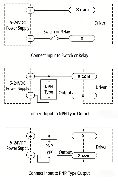
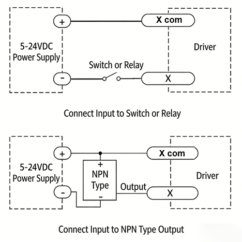
3-channel isolated digital signal input, the function of each input channel can be configured via software or commands, with the correspondence between input signals and functions as follows:
| Signal | Interface | Function |
|---|---|---|
| X0 | X0,Xcom | • General Input (Default) • Pulse / Limit / Home / Emergency Stop / Speed Switch / Interrupt Positioning / Forward Rotation |
| X1 | X1,Xcom | • General Input (Default) • Pulse / Direction / Limit / Home / Emergency Stop / Speed Switch / Interrupt Positioning / Reverse Rotation |
| X2 | X2,Xcom | • General Input (Default) • Limit / Home / Emergency Stop / Speed Switch / Interrupt Positioning |
XCOM is the common positive terminal for single-ended input signals and shall be connected to the positive pole of the power supply.
It only accepts sinking NPN signals.
The figure below illustrates the typical wiring configurations for the X0–X2 input ports.
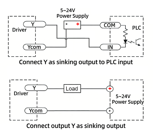
3-channel isolated digital signal output, the function of each output channel can be configured via software or commands, with the correspondence between output signals and functions as follows:
| Signal | Interface | Function |
|---|---|---|
| Y0 | Y0, Ycom | • Alarm Output (Default) • Alarm / Position Reached / Running Status |
| Y1 | Y1, Ycom | • Position Reached Output (Closed Loop Default) • Running Status Output (Open Loop Default) • Alarm / Position Reached / Running Status |
| Y2 | Y2, Ycom | • General Purpose Output (Default) • Alarm / Position Reached / Running Status |
The figure below illustrates the typical wiring configurations for the Y0–Y2 output ports.
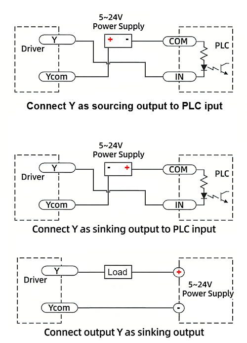
Warning: Output terminal → DC voltage < 30V, Inflow current ≤ 50mA.
CRC Check Routine (C#)
UInt16 Funct_CRC16(unsigned char * puchMsg, UInt16 DataLen)
{
UInt16 i,j,tmp;
UInt16 crcdata=0xFFFF;
for(i=0;i<DataLen;i )
{
crcdata=(*puchMsg)^crcdata;
puchMsg ;
for(j=0;j<8;j )
{
tmp=crcdata&0x0001;
crcdata=crcdata>>1;
if(tmp){
crcdata=crcdata^0xA001;
}
}
}
return crcdata;
}
RS485 Integrated Stepper Motor Commissioning and Control Software:
Modbus Poll
New Software in google drive ![]()
Adampower
Quick Start Guide – Follow the steps below:
1. Extract the zip file, open CommFile folder and Click Step-Config.exe or Adampower.exe
2. Open Project.
3. Click Browse
4. Select the Project.prj in the Project folder, in the same path as CommFile.
5. Double Click the Project.prj path
6. Right Click Modbus_485, and Click Property:
7. Click Property ComNN, Choose COM port, Baud rate and click Save and OK.
8. Start to use software control the RS485 Integrated stepper motor by below buttons:
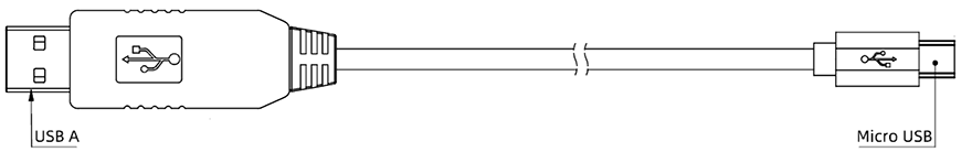
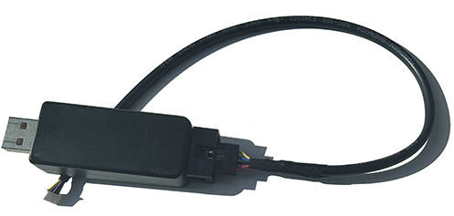
Optional: USB-TTL debugging cable
RS485 Stepper Motor Controller Commands Manual
LED indicator and status:
more Information on detail, please feel free to contact me

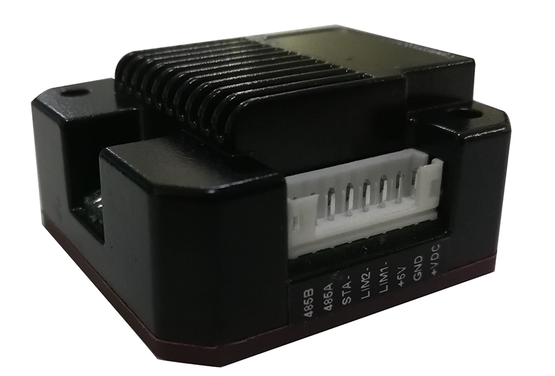
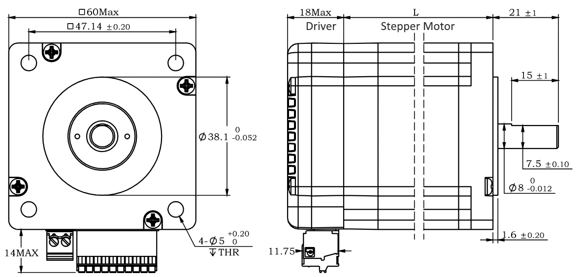
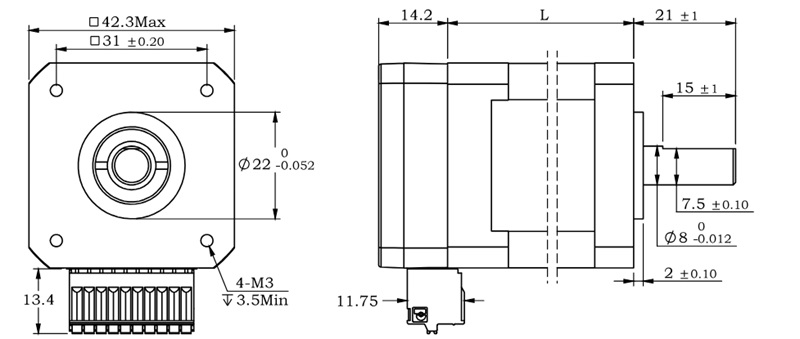
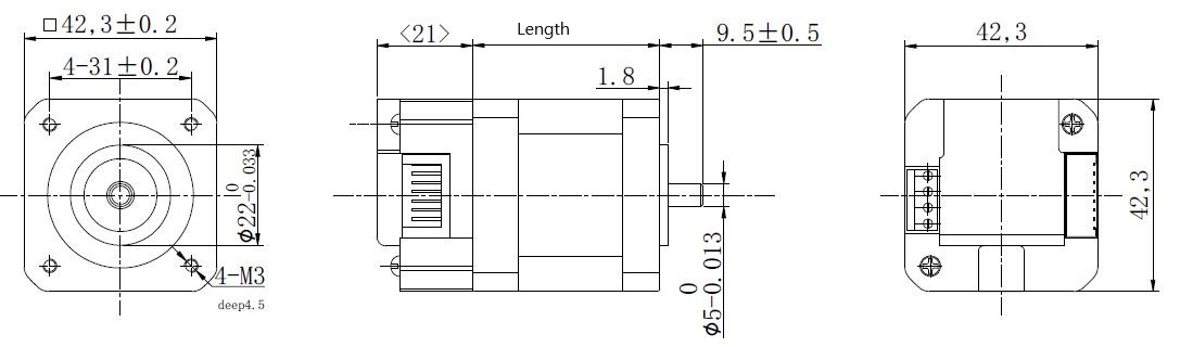
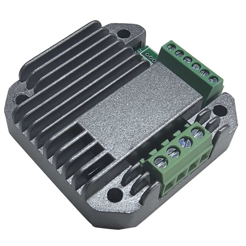
RS485 Serial Stepper Motor Controller, Design for NEMA17 Stepper Motors.
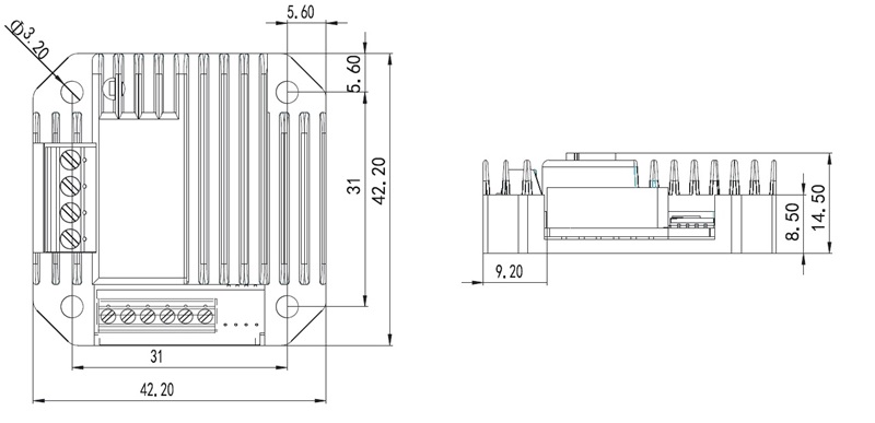
● Miniature size 42.3mmx42.3mm x21mm
● Standard RS485 communication protocol and built-in motion control instructions.
● Multi-axes control, extending up to 32 axes for simultaneous control.
● DC input voltage 12~32VDC, recommended working voltage 24VDC.
● Continuous output current 1.58A max, max peak current 2.2A.
● Integrated design, mounted with 42/39mm stepper motor.
● Low vibration, low noise, stable operation, low motor heating.
● Any micro-step can be set .
● Protection functions such as overvoltage, undervoltage and overcurrent.
● Built-in automatic matching function of motor parameter.
● Serial port RS232/RS485 debugging function.
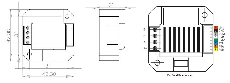
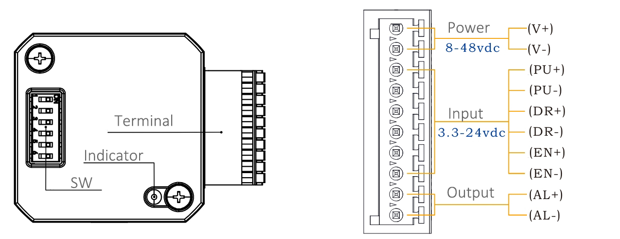
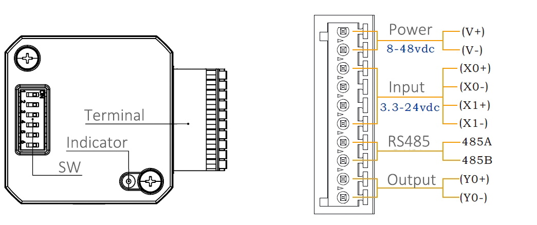
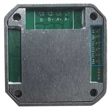
1.VDC: Positive power input: DC voltage 12-32VDC
2.GND: Negative power input: DC voltage GND
3.COM IO signal level common anode common terminal, amplitude 5VDC,
4.LIM1- Reverse limit signal port, valid for rising edge
5.LIM2- Reverse limit signal port, valid for rising edge
6.STA: Start and stop signal port, valid on rising edge
7.RSA: RS485 group A signal
8.RSB: RS485 group B signal
Working Principle:
ADM42 Series RS485 Stepper Motor Controller with NEMA17 size plastic flange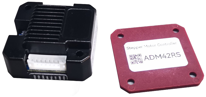
When the RS485 Stepper Motor Controller without this NEMA17 Plastic Flange,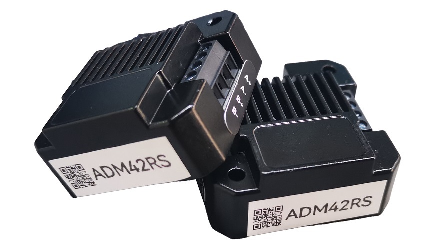
It can be assembled to NEMA17 Stepper Motor directly.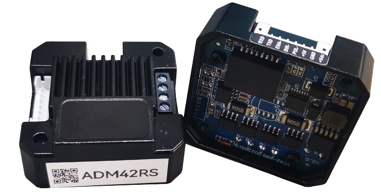
NEMA17 Integrated Stepper Motor, More concise and aesthetically pleasing.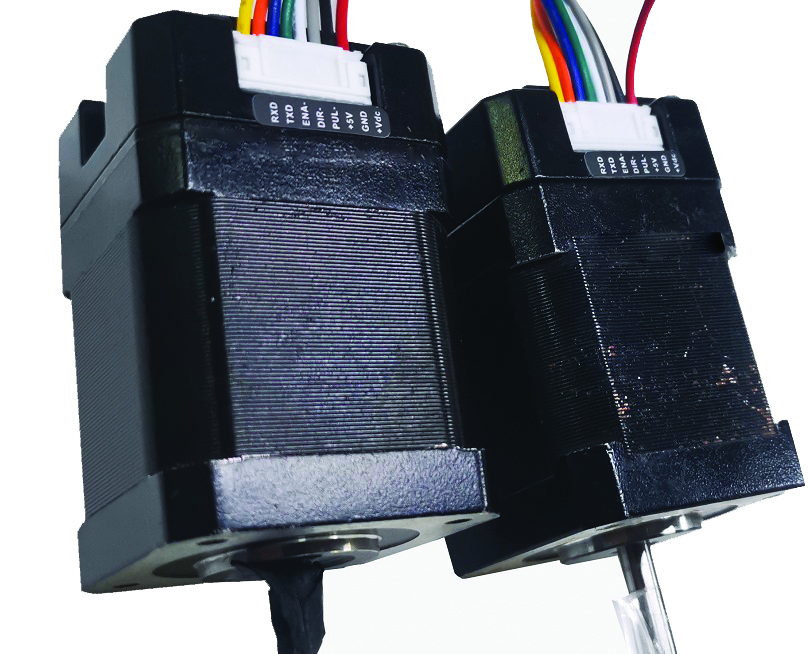
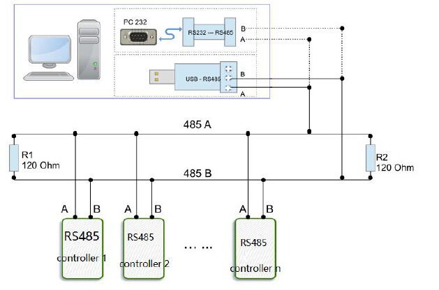
RS485 Stepper Motor Controller, using 6 DIP switch for set the communication baud rate and device ID.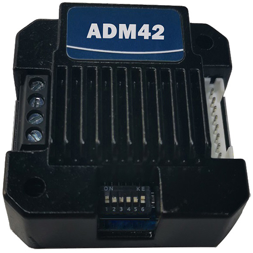
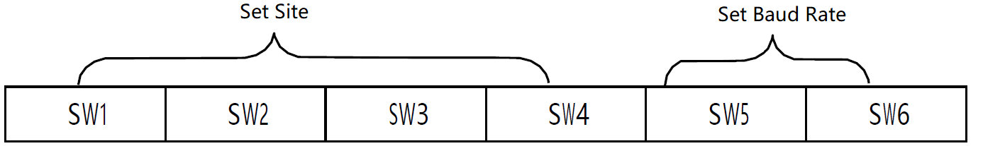
Device ID | SW1 | SW2 | SW3 | SW4 |
Broadcast | ON | ON | ON | ON |
1 | OFF | ON | ON | ON |
2 | ON | OFF | ON | ON |
3 | OFF | OFF | ON | ON |
4 | ON | ON | OFF | ON |
5 | OFF | ON | OFF | ON |
6 | ON | OFF | OFF | ON |
7 | OFF | OFF | OFF | ON |
8 | ON | ON | ON | OFF |
9 | OFF | ON | ON | OFF |
10 | ON | OFF | ON | OFF |
11 | OFF | OFF | ON | OFF |
12 | ON | ON | OFF | OFF |
13 | OFF | ON | OFF | OFF |
14 | ON | OFF | OFF | OFF |
15 | OFF | OFF | OFF | OFF |
Note: The formula for calculating the ID: ID=1*SW1 2*SW2 4*SW3 8*SW4.
The default ID value is 0. broadcast mode accept data but not return data.
Communication baud rate setting:
Baud Rate | SW5 | SW6 |
9600 | ON | ON |
19200 | OFF | ON |
38400 | ON | OFF |
57600 | OFF | OFF |
ADM42S RS485 Serial Stepper Motor Controller Manual
More Information on detail, please feel free to contact me
CRC Check routine by C# :
Uint16 Funct_CRC16(unsigned char * puchMsg, Uint16 DataLen)
{
Uint16 i,j,tmp;
Uint16 crcdata=0xFFFF;
for(i=0;i<DataLen;i )
{
crcdata=(*puchMsg)^crcdata;
puchMsg ;
for(j=0;j<8;j )
{
tmp=crcdata&0x0001;
crcdata=crcdata>>1;
if(tmp){
crcdata=crcdata^0xA001;
}
}
}
returncrcdata;
}
Software Modbus Poll 
AdamPower Software

CANopen Stepper Motor Controller, It supports the CiA301 and CiA402 sub-protocols
of the CANopen protocol.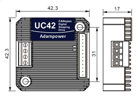
UC42 uses the latest 32-bit DSP digital chip and has advanced drive control algorithms and noise
suppression technology to ensure smooth motor operation. Stable, low noise, and temperature controllable.
Users can set any ID address within 1-255 and any current value within 0-8A through the host computer.
Maximum output peak current of the UC42 bus driver is 2.5A.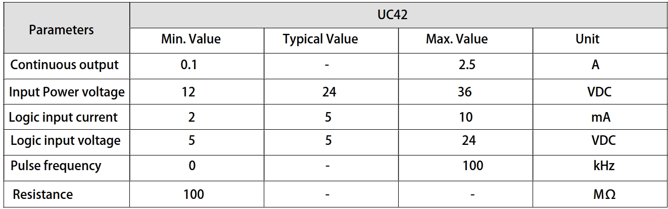
UC42 can be set to 1-256 subdivisions and adopts built-in micro-subdivision technology, which can achieve
high subdivision effects even under low subdivision conditions, ensuring that the motor operates with uniform
step intervals and no large or small step problems.
3 input signal ports and 2 output signal ports, supporting position, speed, and return-to-origin control modes.
with highest communication rate in 1Mbps.
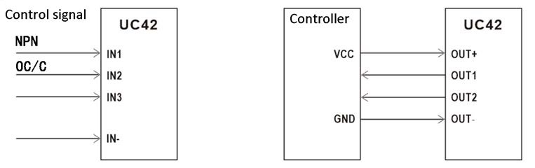
Input signal Wiring diagram and Output Signal wiring diagram↑
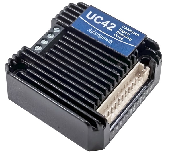
UC42 is designed for NEMA17 stepper motor, we supply NEMA17 integrated stepper motor with
torque 0.35, 0.50 and 0.7Nm:
if just choose UC42 stepper motor controller with requirement for low vibration, please inform us for
setting parameters before sale. 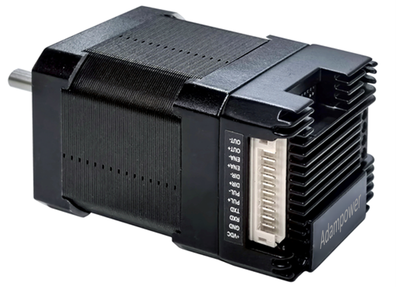
| Model No. | Holding Torqure(Nm) | Motor Length(mm) |
| UC42-03 | 0.35 | 40 |
| UC42-05 | 0.50 | 48 |
| UC42-07 | 0.70 | 60 |
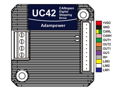
Port Definition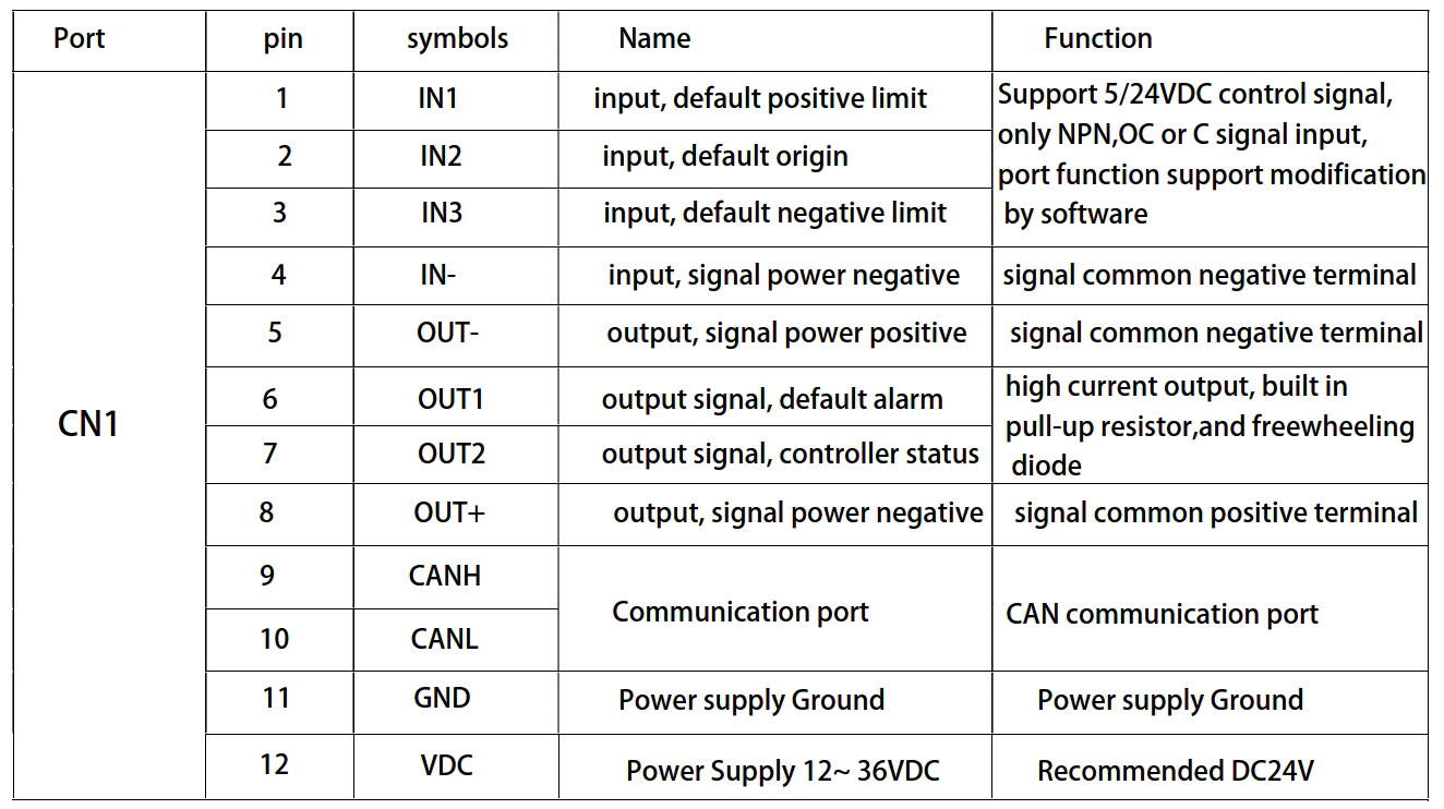
It can be connected to PLC, industrial computer, controller and other host computers with only two
communication lines. Through the built-in motion Control instructions can realize a network of up to
100-axis stepper motors.
especially suitable for long-distance multi-axis applications, which can reduce wiring and enhance
the reliability of drive operation.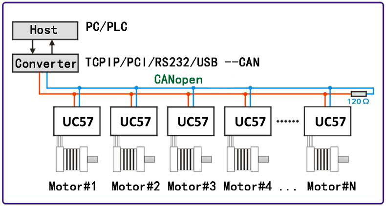
Mainly used in electronic equipment, semiconductors, medical instruments, environmental protection equipment,
automatic detection equipment, small automatic processing equipment and other automation equipment with
multiple motor shaft applications and compact requirements for equipment space
CANopen Standard Command Read and Write: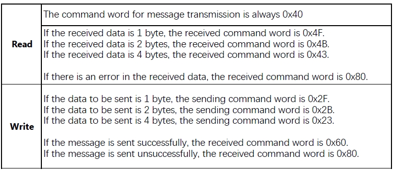
UC42 CANopen Stepper Motor Controller User Manual
CANOpen Software
More Information on detail, please feel free to contact me

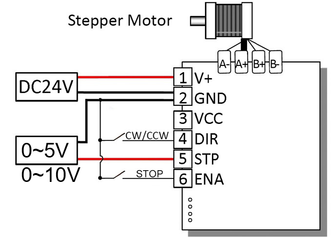
0~5V, 0~10v Analog Voltage type stepper motor driver
 | 510V | |||
| minimum value | Typical value | Maximum value | Unit | |
| Supply Voltage (DC) | 12 | 24 | 24 | VDC |
| Analog Signal Voltage | 0-5 | 0-5 | 0-10 | V |
● Miniature size 42.2mmx42.2mm x14.5mm
● DC input voltage 12~40VDC, recommended working voltage 24VDC.
● Continuous output current 1.4A max, max peak current 2.0A.
● Integrated design, mounted with NEMA17, NEMA23 stepper motor.
● Low vibration, low noise, stable operation, low motor heating.
● Working Speed Range and Analog Signal Voltage can be customized as requirement.
● Adjusting voltage: 0~5V(or 0~10V), corresponding to Speed range, High Speed Range: 0~1000RPM; Low Speed Range: 0~500RPM.
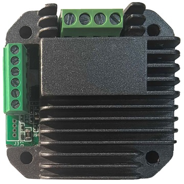
| Pin No. | Name | Description |
| 1 | 24V | Supply voltage: 12-40VDC, Recommend DC24V |
| 2 | GND | Supply Voltage Ground: GND/0V |
| 3 | H/L | Default High Speed Range; Connect GND to Low Speed Range |
| 4 | DIR | The rotation direction of the motor, CW/CCW |
| 5 | STP | The positive pole of the analog voltage current |
| 6 | ENA | Enable the Stepper Motor |
| 7 | DEBUG | Debug port |
Wiring Diagram:
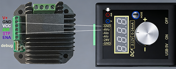
Debug cable:
Analog Voltage Signal 0-5V or 0-10V, Customized Working Speed Range 0-1000RPM for peristaltic pumps requirement.
Both of the two Speed Range for Customized, High Speed Range and Low Speed Range.
Default Adjusting Analog voltage: 0~5V corresponding to Speed range, High: 0~1000RPM; Low: 0~500RPM.
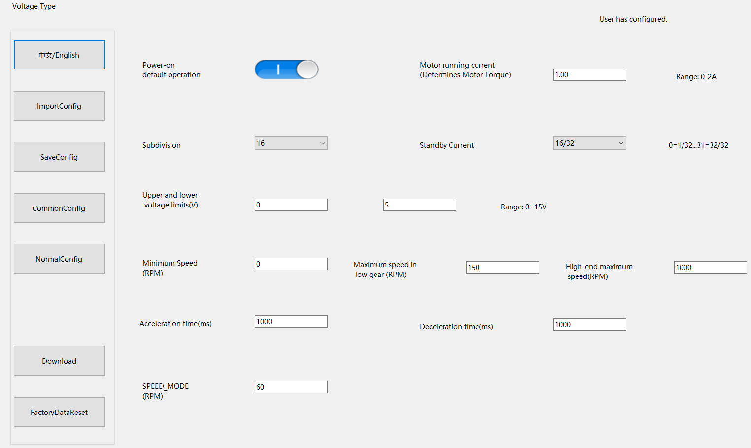
Analog Voltage Type Stepper Motor Driver User Manual
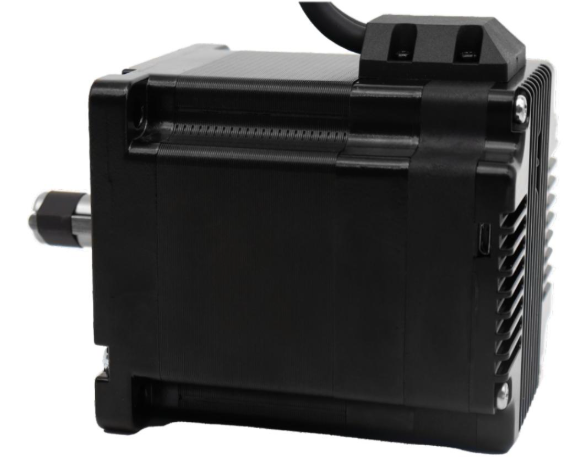
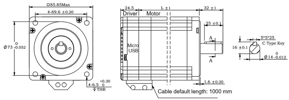
When this NEMA17 Sized Driver assembled with NEMA23 motor via a flange,
an Integrated Stepper Motor is formed: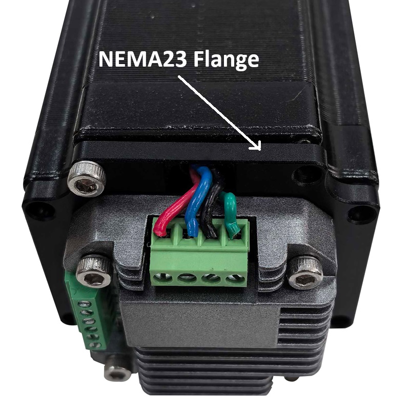
More Information on detail, please feel free to contact me

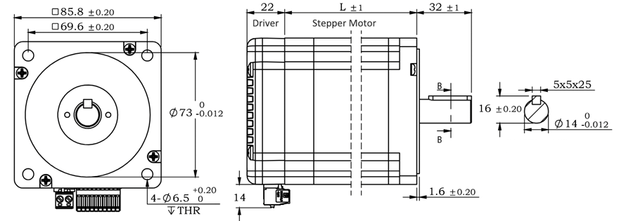
The IM34ET Series Integrated Motors represent a perfect integration of stepper drivers and stepper motors, combining the technologies of both in a single unit. They are fully compatible with 1599-revolution mechanical absolute encoders, which not only save installation space but also streamline wiring connections. By reducing your design and production costs, they stand as the premier choice for your stepper system solutions.
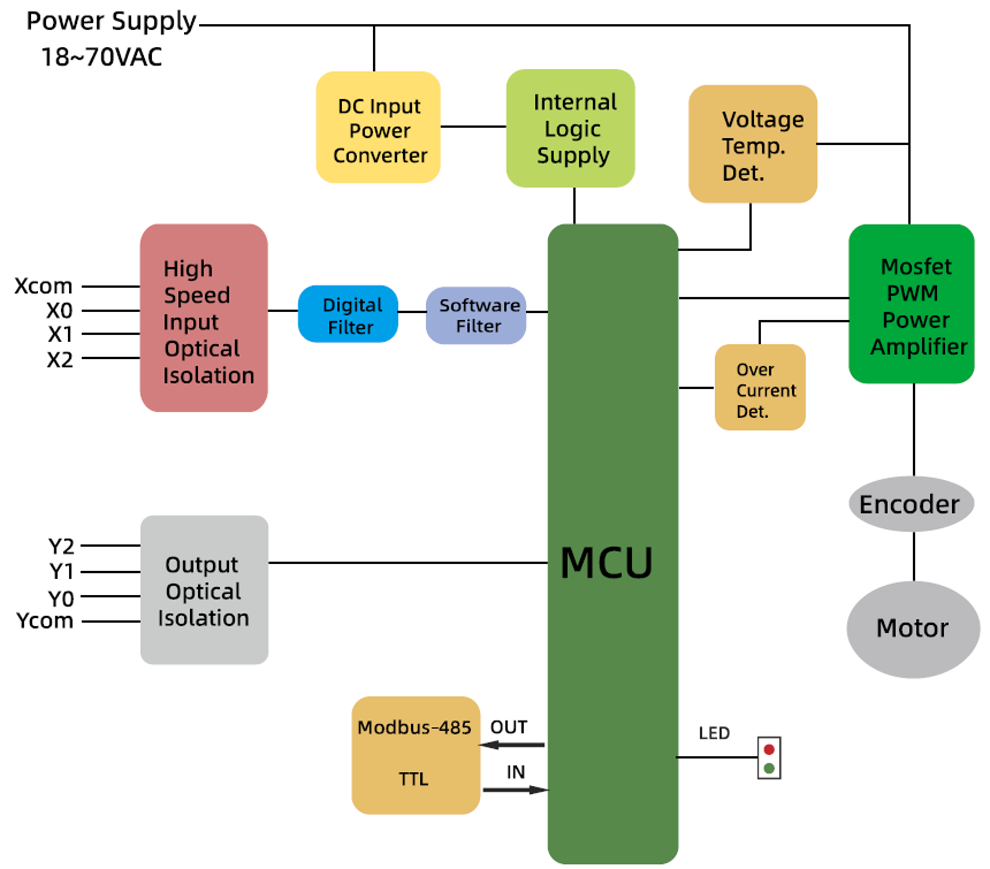
Frame Size: NEMA34
Holding Torque: 4.5–12.5 N·m
Supply Voltage: 18–70 VAC
Supported Protocols: Modbus/RTU, RS485
Built-in Programmable Multi-Turn Feedback: 1599 revolutions; supports user-defined home position with memory, no sensor required
Software Limit Function Supported: More reliable than mechanical limit switches
Closed-Loop Control: 4096-line (16384 counts) encoder feedback
Torque Modes Supported: Homing on collision, constant torque, object gripping
Input Compatibility: 5–24 VDC; Output: Open-collector (OC) output, withstanding voltage up to 30 VDC
Comprehensive Protection Features: Over-voltage, under-voltage, over-current, winding open-circuit, and position deviation protection
Non-Volatile Memory: Configuration parameters stored in the on-chip FLASH of the MCU
Wide Filter Frequency Range: 50 kHz–5 MHz adjustable, factory default at 300 kHz
User-friendly PC interface with full-featured functionality
Motor Parameters
| Model No. | Length L (mm) | Total Length (mm) | Shaft Length (mm) | Shaft Dia. (mm) | Phase Current (A) | Resistance (Ω) | Inductance (mH) | Holding Torque (N.m) | Inertia (g.cm²) | Weight (g) |
|---|---|---|---|---|---|---|---|---|---|---|
| IM3445 | 78.1 | 102.6 | 32 | 14 | 6 | 0.37 | 2.8 | 4.5 | 1800 | 2200 |
| IM3465 | 98.6 | 122.1 | 32 | 14 | 6 | 0.45 | 4.0 | 6.5 | 2800 | 3000 |
| IM3485 | 117.6 | 142.1 | 32 | 14 | 6 | 0.59 | 5.5 | 8.5 | 3600 | 3700 |
| IM34125 | 156.1 | 180.6 | 32 | 14 | 6 | 0.679 | 8.2 | 12.5 | 5400 | 5500 |
RS485 Multi-turn Absolute Encoder type Integrated Stepper Motor
Terminal Definition
| Terminal | Color | Name | Description |
|---|---|---|---|
| 1 | Red | V | 24~100VDC(or 18-70VAC) |
| 2 | Black | V- | GND |
| 3 | Yellow | X com | COM /VCC COM, compatible with 5–24 VDC |
| 4 | Yel/BLK | X0 | 3 Programmable Inputs (Active Low) Port functions configurable via commands or host computer. Pulse Mode: X0 = Pulse, X1 = Direction |
| 5 | Blue | X1 | |
| 6 | Blu/BLK | X2 | |
| 7 | Green | Y2 | Y0: Default alarm output, Normally Closed (NC), Y1: Default position reached output, Normally Closed (NC) Y2: Undefined,Users may configure or redefine the functions of the corresponding ports via commands. Y2 can be customized to input X3 upon request before delivery; it defaults to an output port. |
| 8 | Gre/BLK | Y1 | |
| 9 | Purple | Y0 | |
| 10 | Pur/BLK | Y com | COM GND |
| 11 | Orange | 485A | RS485 Communication port, default baud rate is 115200 |
| 12 | Ora/BLK | 485B |
3-channel isolated digital signal input, the function of each input channel can be configured via software or commands, with the correspondence between input signals and functions as follows:
| Signal | Interface | Function |
|---|---|---|
| X0 | X0,Xcom | • General Input (Default) • Pulse / Limit / Home / Emergency Stop / Speed Switch / Interrupt Positioning / Forward Rotation |
| X1 | X1,Xcom | • General Input (Default) • Pulse / Direction / Limit / Home / Emergency Stop / Speed Switch / Interrupt Positioning / Reverse Rotation |
| X2 | X2,Xcom | • General Input (Default) • Limit / Home / Emergency Stop / Speed Switch / Interrupt Positioning |
XCOM is the common positive terminal for single-ended input signals and shall be connected to the positive pole of the power supply.
It only accepts sinking NPN signals.
The figure below illustrates the typical wiring configurations for the X0–X2 input ports.
3-channel isolated digital signal output, the function of each output channel can be configured via software or commands, with the correspondence between output signals and functions as follows:
| Signal | Interface | Function |
|---|---|---|
| Y0 | Y0, Ycom | • Alarm Output (Default) • Alarm / Position Reached / Running Status |
| Y1 | Y1, Ycom | • Position Reached Output (Closed Loop Default) • Running Status Output (Open Loop Default) • Alarm / Position Reached / Running Status |
| Y2 | Y2, Ycom | • General Purpose Output (Default) • Alarm / Position Reached / Running Status |
The figure below illustrates the typical wiring configurations for the Y0–Y2 output ports.
Warning: Output terminal → DC voltage < 30V, Inflow current ≤ 50mA.
CRC Check Routine (C#)
UInt16 Funct_CRC16(unsigned char * puchMsg, UInt16 DataLen)
{
UInt16 i,j,tmp;
UInt16 crcdata=0xFFFF;
for(i=0;i<DataLen;i )
{
crcdata=(*puchMsg)^crcdata;
puchMsg ;
for(j=0;j<8;j )
{
tmp=crcdata&0x0001;
crcdata=crcdata>>1;
if(tmp){
crcdata=crcdata^0xA001;
}
}
}
return crcdata;
}
RS485 Integrated Stepper Motor Commissioning and Control Software:
Modbus Poll
Adampower
Quick Start Guide – Follow the steps below:
1. Extract the zip file, open CommFile folder and Click Step-Config.exe or Adampower.exe
2. Open Project.
3. Click Browse
4. Select the Project.prj in the Project folder, in the same path as CommFile.
5. Double Click the Project.prj path
6. Right Click Modbus_485, and Click Property:
7. Click Property ComNN, Choose COM port, Baud rate and click Save and OK.
8. Start to use software control the RS485 Integrated stepper motor by below buttons:
Optional: USB-TTL debugging cable
RS485 Stepper Motor Controller Commands Manual
LED indicator and status:
more Information on detail, please feel free to contact me

| Step Accuracy: | ±5% | Resistance Accuracy: | ±10% |
|---|---|---|---|
| Inductance Accuracy: | ±20% | Temperature Rise: | 80°C MAX |
| Ambient Temperature Range: | -20°C~ 50°C | Storage Temperature Range: | -30°C~ 60°C |
| Insulation Resistance: | 100M Ω MIN. 500V DC | Dielectric Strength: | 500V AC 1min |
| Radial Play: | 0.02mm MAX. (450g Load) | End Play: | 0.08mm MAX. (450g Load) |
| Max. Radial Force: | 20N | Max. Axial Force: | 2N |
NEMA17 Stepper Motor, Closed Loop stepper motor
Electrical Specifications:
| Mode No. | Step Angle | Motor Length mm | Rated Current A | Holding Torque (MIN) N.m | Motor Weight kg | Shaft Dia. mm |
| 17H249-01ED1000 | 1.8 | 67.1 | 0.6 | 0.48 | 0.36 | 5.0 |
| 17H249-02ED1000 | 1.8 | 67.1 | 1.2 | 0.48 | 0.36 | 5.0 |
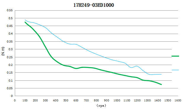
| 17H249-03ED1000 | 1.8 | 67.1 | 1.8 | 0.48 | 0.36 | 5.0 |
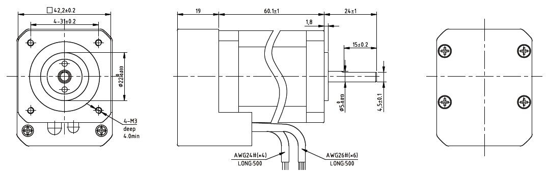
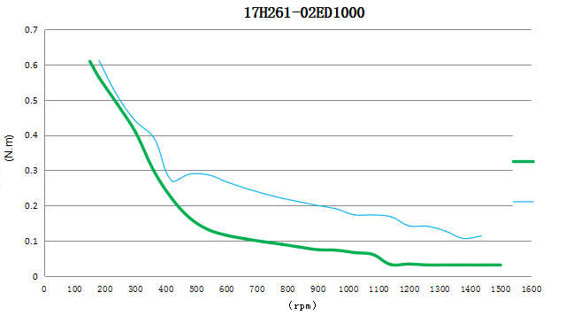
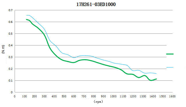
| 17H261-01ED1000 | 1.8 | 79.1 | 0.6 | 0.72 | 0.50 | 5.0 |
| 17H261-02ED1000 | 1.8 | 79.1 | 1.2 | 0.72 | 0.50 | 5.0 |
| 17H261-01ED1000 | 1.8 | 79.1 | 1.8 | 0.72 | 0.50 | 5.0 |
Stepper motor with 1000 Line Encoder:
1. Black : EGED
2. RED : 5VCC
3. Blue/White : EA-
4 Blue : EA
5. Orange/White : EB-
6. Orange : EB
Mechanical Dimensions and Wiring Diagram:
NEMA17 Stepper Motor with encoder, 17H249ED1000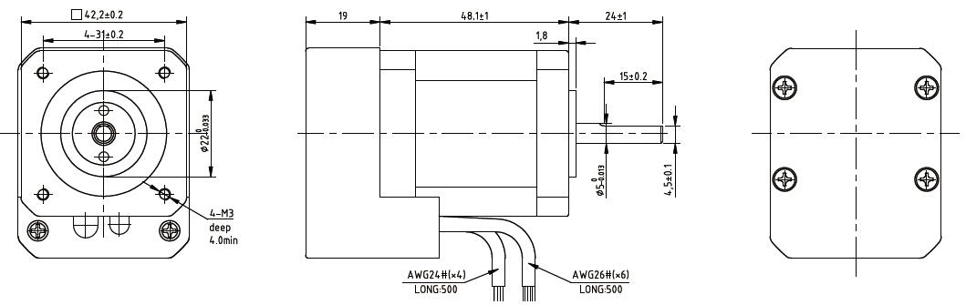
DC24V Torque Speed Curve: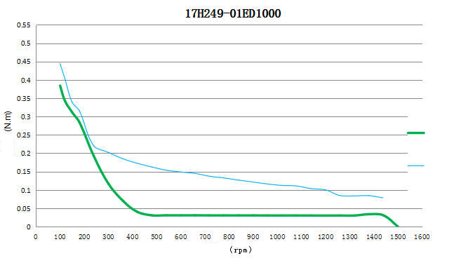

NEMA17 Stepper Motor with encoder, 17H261ED1000:
DC24V Torque Speed Curve: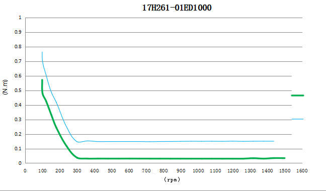
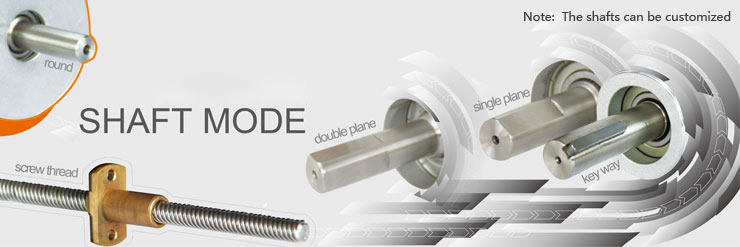
Lead Wire Mode Options:
Shaft Mode can be customized as the requirement.
More Information on detail, please feel free to contact me

The IS14 series integrated motor is the perfect combination of drive and stepper motor,
which perfectly integrates stepper motor and drive technology, also built in a battery free
1023 turn mechanical absolute value encoder, it can save installation space,
Simultaneously saving design and production costs, supporting RS485 instruction control.
| Item | Specifications |
| Stepper Motor Size | NEMA14 |
| Encoder type | 1023 ring absolute encoder |
| Working voltage | 8-36V |
| Driver Current | 0.2-2.0A |
| Velocity range | Up to 3000RPM |
| Control Method | RS485 √ Pulse& Direction, Twin-Pulse, I/O, Built-in Program |
| Torque value | 0.1 - 0.4Nm |
| Nonvolatile storage | Configuration parameters are stored in FLASH inside the MCU |
| DI and DO | 2 DI, 1 DO |
| Protection | Overvoltage, undervoltage, overcurrent, open winding, position deviation |
| Digital Input (2) | Receive 3.3-24VDC | ||
| Digital Output(1) | Maximum withstand voltage of 30V, | ||
| Maximum input or output current 30mA | |||
Motor Parameters
| Model No. | length mm L | Shaft length mm | Shaft dia. mm | Phase current A | Resistance Ω | inductance mH | Hold torque N.m | Inertia g.cm² | Weight g |
| IS14010 | 52 | 24 | 5 | 1.0 | 2.55 | 2.0 | 0.1 | 12 | 240 |
| IS14020 | 62 | 24 | 5 | 1.5 | 1.65 | 2.1 | 0.2 | 20 | 300 |
| IS14040 | 80 | 24 | 5 | 1.8 | 1.85 | 2.8 | 0.4 | 35 | 350 |
Wiring Diagram:
Terminal Definition
| Terminal | Name | Description | |
| 1 | V | 8-36VDC | |
| 2 | V- | GND | |
| 3 | X0 (PU ) | Optoelectronic isolation, differential, High level can directly receive 3.3-24VDC, with a minimum pulse width of 2us, The maximum pulse frequency is 400KHz, which can be used as a universal input port for Pulse/Direction | |
| 4 | X0-(PU-) | ||
| 5 | X1 (DR ) | ||
| 6 | X1-(DR-) | ||
| 7 | X2(EN ) | Optoelectronic isolation, differential, High level can directly receive 3.3-24VDC, with a minimum pulse width of 100us, The maximum pulse frequency is 10KHz, which can be used as a universal input port for Enable | |
| 8 | X2-(EN-) | ||
| 9 | Y0 (AL ) | The default alarm output port can detect the driver alarm status and provide feedback to the main station. Other functions can be set through communication | |
| 10 | Y0-(AL-) | ||
| 11 | 485A | RS485 Communication port, default baud rate is 115200 | |
| 12 | 485B | ||
Block Diagram:
2 Input signals can directly receive 3.3-24V DC levels at high levels, Max. frequency of 400KHZ.
X0: pulse input, IO start/stop, limit, direction, universal input.
X1 pulse input, IO start/stop, limit, direction, universal input.
1 Output signal, maximum withstand voltage 30V, maximum input or output current 30mA
Y0 : alarm output, universal output, and factory default alarm output.
LED indicator and status:
CRC Check routine by C# :
Uint16 Funct_CRC16(unsigned char * puchMsg, Uint16 DataLen)
{
Uint16 i,j,tmp;
Uint16 crcdata=0xFFFF;
for(i=0;i<DataLen;i )
{
crcdata=(*puchMsg)^crcdata;
puchMsg ;
for(j=0;j<8;j )
{
tmp=crcdata&0x0001;
crcdata=crcdata>>1;
if(tmp){
crcdata=crcdata^0xA001;
}
}
}
returncrcdata;
}
Software Modbus Poll
Software Adampower
1. Extract the zip file, open CommFile folder and Click Step-Config.exe or Adampower.exe
2. Open Project.
3. Click Browse
4. Select the Project.prj in the Project folder, in the same path as CommFile.
5. Double Click the Project.prj path
6. Right Click Modbus_485, and Click Property:
7. Click Property ComNN, Choose COM port, Baud rate and click Save and OK.
8. Start to use software control the RS485 Integrated stepper motor by below buttons:
RS485 Stepper Motor Controller Manual
~~~~~~~~~~~~~~~~~~~~~~~~~~~~~~~~~~~~~~~~~~~~~~~~~~~~~~~~~~~~~~~~~~~~~~~~~~~~~~~~~~~~
Block Diagram:
2 Input signals can directly receive 3.3-24V DC levels at high levels, Max. frequency of 400KHZ.
X0: pulse input, IO start/stop, limit, direction, universal input.
X1 pulse input, IO start/stop, limit, direction, universal input.
...
1 Output signal, maximum withstand voltage 30V, maximum input or output current 30mA
Y0 : alarm output, universal output, and factory default alarm output.
LED indicator and status:

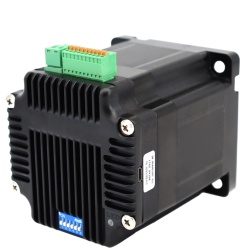
IRO23 is a high-integrated and compact size stepper driver. It adopts standard RS485 communication
protocol, can be connected with PLC, HMI, industrial computer and other upper computer with only two
communication lines. Up to 32 axes of motion platform networking can be achieved with its built-in motion
control commands.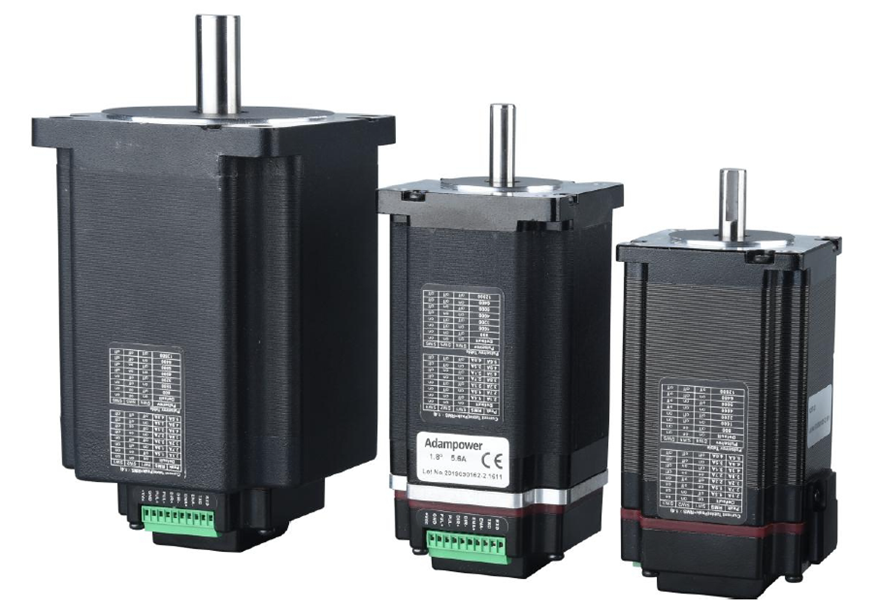
IRO can be set to 1-256 subdivisions and adopts built-in micro-subdivision technology, which can achieve
high subdivision effects even under low subdivision conditions, ensuring that the motor operates with uniform
step intervals and no large or small step problems.
1 Electrical Characteristics
| Explanation | IRO23 | |||
|---|---|---|---|---|
| Minimum Value | Typical Value | Maximal Value | Unit | |
| Continuous output current | 0.5 | - | 5.6 | A |
| Power Supply Voltage (DC) | 15 | 24/36 | 50 | VDC |
| Control signal input current | 6 | 10 | 16 | mA |
| Control signal input Voltage | - | 5 | - | VDC |
| Overvoltage point | 54 | 55 | 56 | VDC |
| Step frequency | 1 | - | 1000 | KHz |
| Insulation Resistance | 100 | - | - | MΩ |
2.2 Suitable for Standard Motor
The integrated driver can be used for NEMA23 open-loop hybrid stepper motors and linear screw stepper motors of different specifications from major motor manufacturers.
The driver can be sold separately.
If you need to purchase our driver and motor complete set of products, we generally recommend the following two standard models.
Other models of stepper motors or suitable screw stepper motors can be customized according to customer needs.
| Model No. | Holding Torque (N.m) | Motor Length (mm) | Driver Thickness (mm) | Weight (kg) |
|---|---|---|---|---|
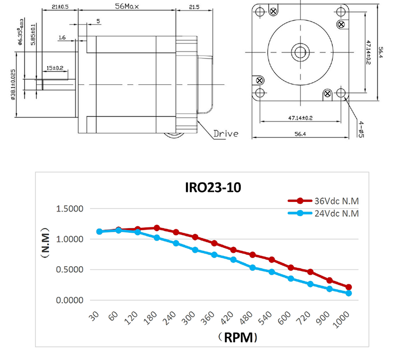
| IRO23-10 | 1.0 | 56±1 | 21.5±1 | 0.9 |
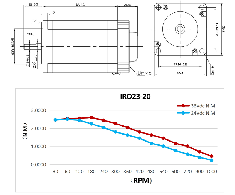
| IRO23-20 | 2.0 | 80±1 | 21.5±1 | 1.2 |
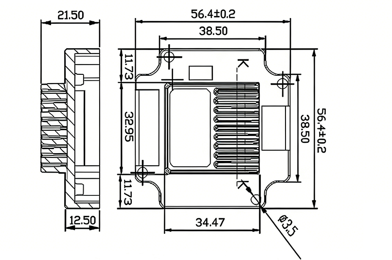
IRO23 RS485 stepper motor driver dimensions:
IRO23-10 RS485 integrated stepper motor specifications and motor torque-frequency characteristic curve:
IRO23-20 RS485 integrated stepper motor specifications and motor torque-frequency characteristic curve:
2.3 Use Environment
| Cooling Mode | Natural Cooling or forced air cooling |
|---|---|
Service Environment Occasion | Keep away from heating equipment, dust, oil mist, high humidity & strong vibration. |
| Temperature | -10℃ ~ 50℃ |
| Humidity | 40 ~ 90% RH |
| Vibration | 5.9 m/s² MAX |
| Storage temperature | -20℃ ~ 60℃ |
| Use Elevation | Below 1000 meters |
| Weight | 0.7 KG |
The control signal and the power supply input port use the 8Pin 2.0 mm terminal.
| Pin | Signal Name | Function Description |
|---|---|---|
| 1 | VDC | Power positive input: DC VOLTAGE 15-50VDC |
| 2 | GND | Negative power input: GND of DC voltage |
| 3 | PUL | Receiving level 5VDC, pulse control signal input (negative) (left limit) |
| 4 | PUL- | - |
| 5 | DIR | Receiving level 5VDC, direction control signal input (negative) (back to zero) |
| 6 | DIR- | - |
| 7 | ENA | Receiving level 5VDC, enable control signal input (negative) (right limit) |
| 8 | ENA- | - |
| 9 | TXD | Serial port RS485 TXD |
| 10 | RXD | RXD serial port RS485 |
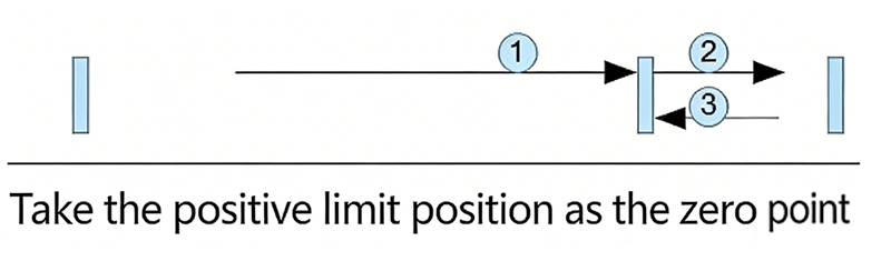
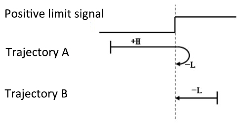
Return to Zero with Positive Limit Signal as Zero
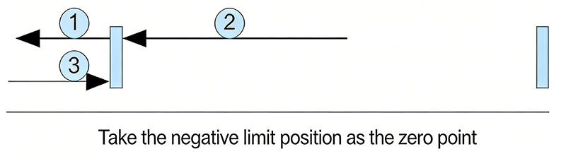
Return to Zero with Negative Limit Signal as Zero
IRO23 RS-485 Stepper Motor Controller User Manual
Software Modbus Poll
AdamPower Software
More Information on detail, please feel free to contact me

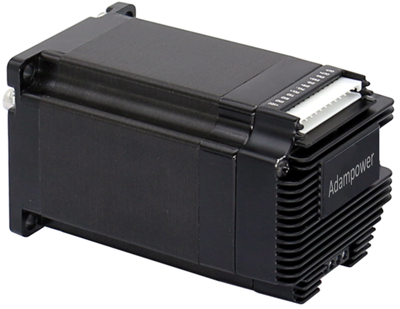
AR57 is a high-integrated and compact size stepper driver. It adopts standard RS485 communication
protocol, can be connected with PLC, HMI, industrial computer and other upper computer with only two
communication lines. Up to 32 axes of motion platform networking can be achieved with its built-in motion
control commands.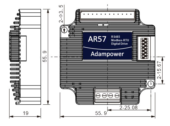
AR57 can be set to 1-256 subdivisions and adopts built-in micro-subdivision technology, which can achieve
high subdivision effects even under low subdivision conditions, ensuring that the motor operates with uniform
step intervals and no large or small step problems.
Can be set between 1-256 subdivisions, with uniform motor step spacing; Stable output at 1/12 rpm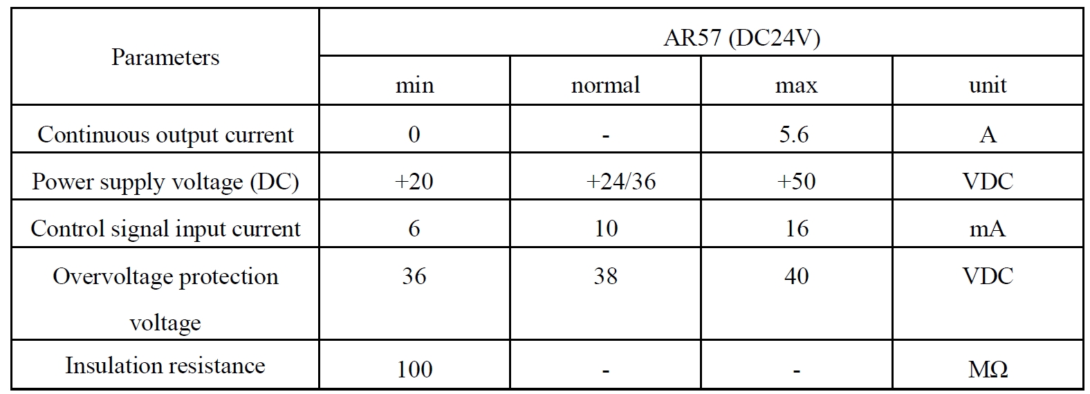
AR57 is designed for NEMA23 stepper motor.
The NEMA23 integrated stepper motor with torque 1.0 and 2.0Nm:
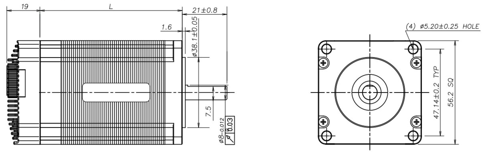
| Model No. | Holding Torque(Nm) | Motor Length L(mm) | Shaft diameter(mm) | Encoder Type |
| AR57-10 | 1.0 | 56mm | 8 | 1000 line Magnetic Encoder |
| AR57-20 | 2.0 | 76mm | 8 | |
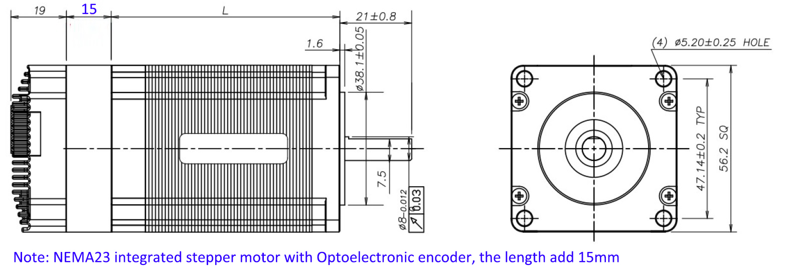
| NEAM23 Integrated stepper motor with Optical Encoder, the length will add 15mm | ||||
| AR57-10L | 1.0 | 56mm | 8 | 1000 line Optical Encoder |
| AR57-20L | 2.0 | 76mm | 8 | |
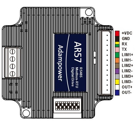
Port Definition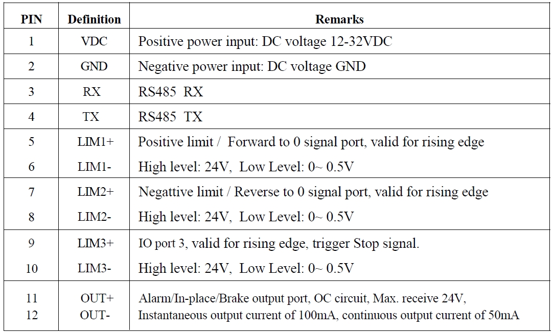
OUT /OUT- as defferential output port, Max.receive voltage is DC24V, and instaneous ouput
current is 100mA, continuous output current is 50mA.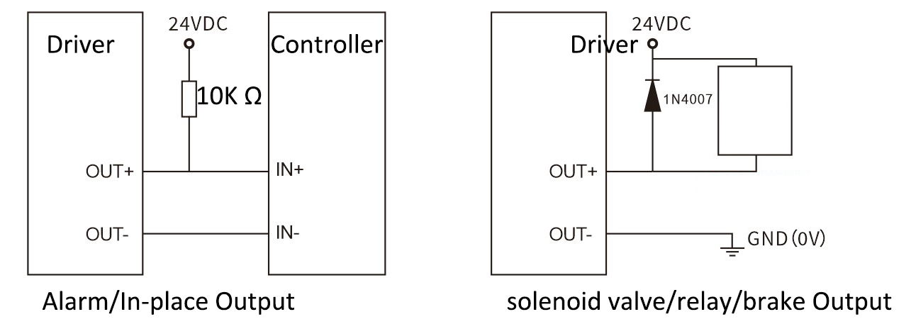
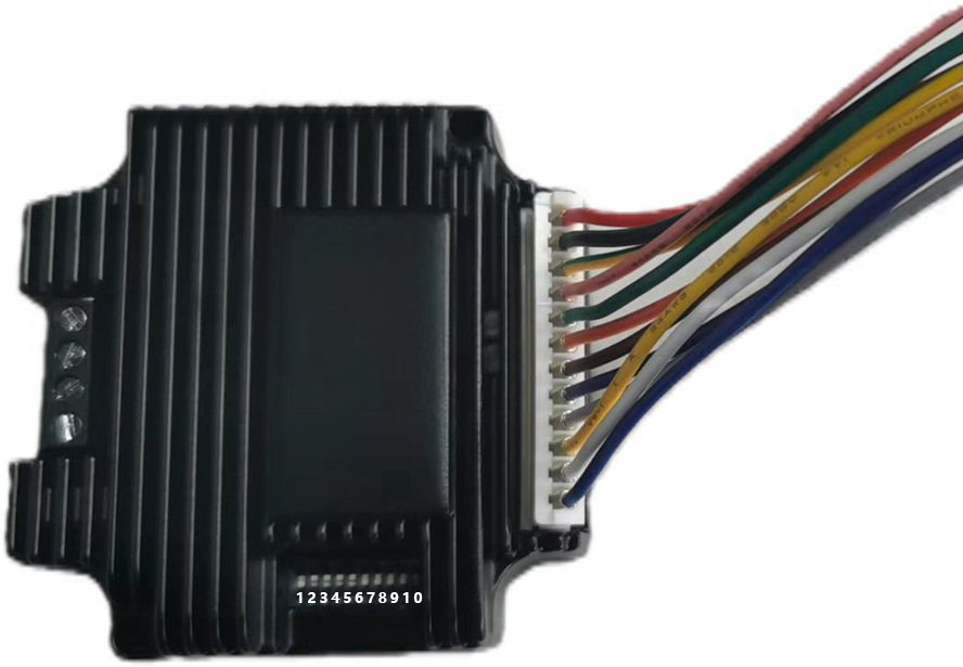
Set ID address, Baud Rate and Ouptut current by SW1~SW10: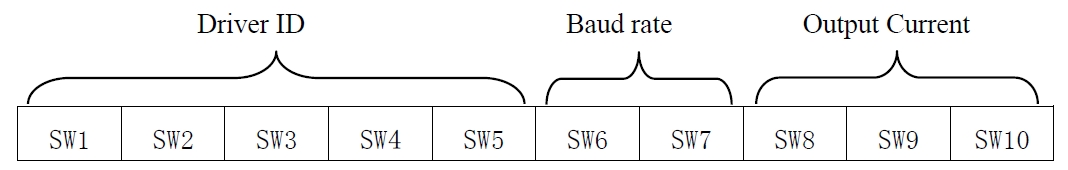
Set ID address:
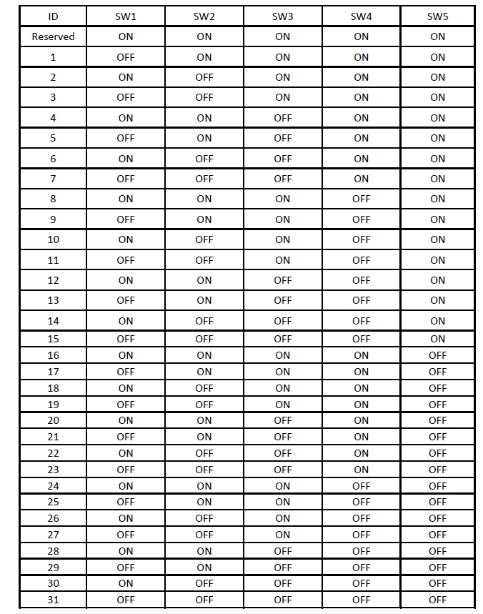
Note: The formula for calculating the ID table is: ID=1*SW1 2*SW2 4*SW3 8*SW4 16*SW5.
The default ID is 0, 0 means broadcast address for global control
Set Baud Rate:
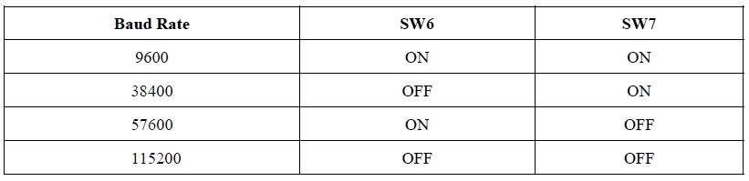
Note: When the communication baud rate in the table cannot meet the usage requirements, the baud rate can be
customized by the host computer when SW6 and SW7 are turned ON.
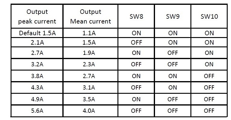
Set Output Current:
Zero-return function with two trajectory A and when limit signal is triggered and not: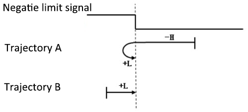
AR57 Modbus Stepper Motor Controller User Manual
Software Modbus Poll
AdamPower Software
More Information on detail, please feel free to contact me

AR42 is a high-integrated and compact size stepper driver. It adopts standard RS485 communication
protocol, can be connected with PLC, HMI, industrial computer and other upper computer with only two
communication lines. Up to 32 axes of motion platform networking can be achieved with its built-in motion
control commands.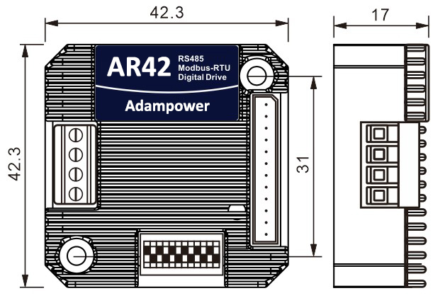
AR42 can be set to 1-256 subdivisions and adopts built-in micro-subdivision technology, which can achieve
high subdivision effects even under low subdivision conditions, ensuring that the motor operates with uniform
step intervals and no large or small step problems.
Can be set between 1-256 subdivisions, with uniform motor step spacing; Stable output at 1/12 rpm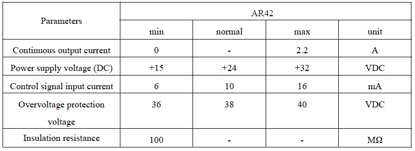
AR42 is designed for NEMA17 stepper motor, The NEMA17 integrated stepper motor with
torque 0.35, 0.50 and 0.7Nm:
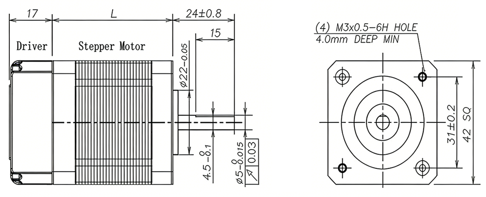
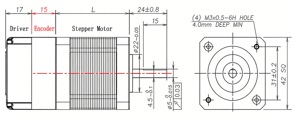
| Model No. | Holding Torque(Nm) | Motor Length L(mm) | Shaft diameter(mm) | Encoder Type |
| AR42-03 | 0.35 | 40mm | 5 | 1000 line Magnetic Encoder |
| AR42-05 | 0.50 | 48mm | 5 | |
| AR42-07 | 0.70 | 60mm | 5 | |
| NEAM23 Integrated stepper motor with Optical Encoder, the length will add 15mm | ||||
| AR42-03L | 0.35 | 40mm | 5 | 1000 line Optical Encoder |
| AR42-05L | 0.50 | 48mm | 5 | |
| AR42-07L | 0.70 | 60mm | 5 | |
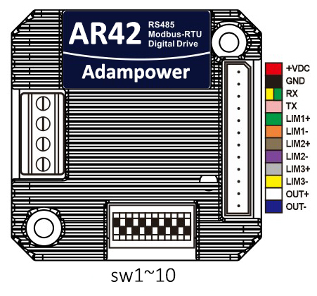
Port Definition
OUT /OUT- as defferential output port, Max.receive voltage is DC24V, and instaneous ouput
current is 100mA, continuous output current is 50mA.
Set ID address, Baud Rate and Ouptut current by SW1~SW10:
Zero-return function with two trajectory A and when limit signal is triggered and not:
AR42 Modbus Stepper Motor Controller User Manual
Software Modbus Poll
AdamPower Software
More Information on detail, please feel free to contact me

| Step Accuracy: | ±5% | Resistance Accuracy: | ±10% |
|---|---|---|---|
| Inductance Accuracy: | ±20% | Temperature Rise: | 80°C MAX |
| Ambient Temperature Range: | -20°C~ 50°C | Storage Temperature Range: | -30°C~ 60°C |
| Insulation Resistance: | 100M Ω MIN. 500V DC | Dielectric Strength: | 500V AC 1min |
| Radial Play: | 0.02mm MAX. (450g Load) | End Play: | 0.08mm MAX. (450g Load) |
| Max. Radial Force: | 20N | Max. Axial Force: | 2N |
NEMA23 Stepper Motor, 1.8° step angle stepper motor
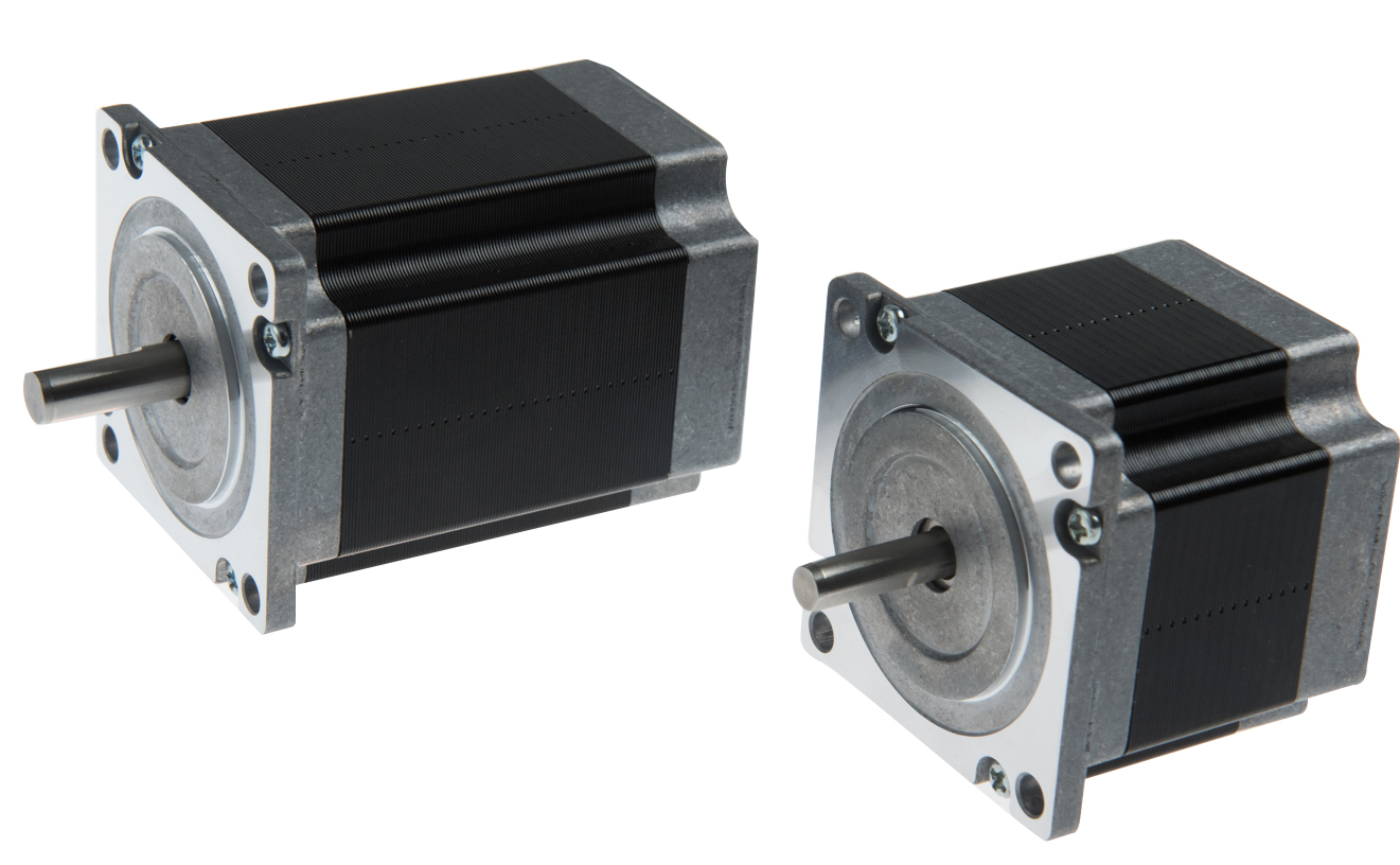
Electrical Specifications:
| Mode No. | Step Angle | Motor Length mm | Rated Voltage v | Rated Current A | Phase Resistance Ω | Phase Indutance Mh | Holding Torque (MIN) N.cm | Detent Torque (MAX) N.cm | Rotor Torque g.cm2 | Lead Wire | Motor Weight kg | Shaft Dia. mm |
| 23HS4406 | 1.8 | 41 | 7.44 | 0.62 | 12 | 24 | 55 | 2.5 | 150 | 4 | 0.47 | 6.35 |
| 23HS4610 | 1.8 | 41 | 5.2 | 1 | 5.2 | 5.5 | 40 | 2.5 | 15O | 6 | 0.47 | 6.35 |
| 23HS4620 | 1.8 | 41 | 2.8 | 2 | 1.4 | 1.4 | 39 | 2.1 | 120 | 6 | 0.45 | 6.35 |
| 23HS4428 | 1.8 | 41 | 2 | 2.8 | 0.7 | 1.4 | 55 | 2.1 | 120 | 4 | 0.45 | 6.35 |
| 23HS4630 | 1.8 | 41 | 1.9 | 3 | 0.63 | 0.6 | 39 | 2.1 | 120 | 6 | 0.45 | 6.35 |
| 23HS5610 | 1.8 | 51 | 6.6 | 1 | 6.6 | 8.2 | 72 | 3.6 | 275 | 6 | 0.65 | 6.35 |
| 23HS5620 | 1.8 | 51 | 3.3 | 2 | 1.65 | 2.2 | 72 | 3.6 | 275 | 6 | 0.65 | 6.35 |
| 23HS5425 | 1.8 | 51 | 3 | 2.5 | 1.2 | 3.2 | 110 | 2.8 | 190 | 4 | 0.52 | 6.35 |
| 23HS5428 | 1.8 | 51 | 2.3 | 2.8 | 0.83 | 2.2 | 101 | 3.6 | 275 | 4 | 0.65 | 6.35 |
| 23HS5630 | 1.8 | 51 | 2.2 | 3 | 0.74 | 0.9 | 72 | 3.6 | 275 | 6 | 0.65 | 6.35 |
| 23HS6610 | 1.8 | 56 | 7.4 | 1 | 7.4 | 10 | 90 | 4 | 300 | 6 | 0.7 | 6.35 |
| 23HS6620 | 1.8 | 56 | 3.6 | 2 | 1.8 | 2.5 | 90 | 4 | 300 | 6 | 0.7 | 6.35 |
| 23HS6425 | 1.8 | 56 | 3.25 | 2.5 | 1.3 | 4.2 | 110 | 3.5 | 280 | 4 | 0.68 | 6.35 |
| 23HS6430 | 1.8 | 56 | 2.4 | 3 | 0.8 | 2.4 | 110 | 3.5 | 280 | 4 | 0.68 | 6.35 |
| 23HS6630 | 1.8 | 56 | 2.3 | 3 | 0.75 | 1.1 | 90 | 4 | 300 | 6 | 0.7 | 6.35 |
| 23HS6442 | 1.8 | 56 | 1.68 | 4.2 | 0.4 | 1.2 | 110 | 3.5 | 280 | 4 | 0.68 | 6.35 |
| 23HS7410 | 1.8 | 64 | 7.5 | 1 | 7.5 | 20 | 150 | 5 | 380 | 4 | 0.85 | 6.35 |
| 23HS7425 | 1.8 | 64 | 3.75 | 2.5 | 1.5 | 4.5 | 150 | 5 | 380 | 4 | 0.85 | 6.35 |
| 23HS7430 | 1.8 | 64 | 2.4 | 3 | 0.8 | 2.3 | 150 | 5 | 380 | 4 | 0.85 | 6.35 |
| 23HS7442 | 1.8 | 64 | 2.31 | 4.2 | 0.55 | 1.2 | 150 | 5 | 380 | 4 | 0.85 | 6.35 |
| 23HS8610 | 1.8 | 76 | 8.6 | 1 | 8.6 | 14 | 135 | 6.8 | 480 | 6 | 1 | 6.35 |
| 23HS8615 | 1.8 | 76 | 6.75 | 1.5 | 4.5 | 7.8 | 140 | 6 | 440 | 6 | 1.05 | 6.35 |
| 23HS8620 | 1.8 | 76 | 4.5 | 2 | 2.25 | 3.6 | 135 | 6.8 | 480 | 6 | 1 | 6.35 |
| 23HS8425 | 1.8 | 76 | 4.5 | 2.5 | 1.8 | 6.5 | 180 | 6 | 440 | 4 | 1.05 | 6.35 |
| 23HS8630 | 1.8 | 76 | 3 | 3 | 1 | 1.6 | 135 | 6.8 | 480 | 6 | 1 | 6.35 |
| 23HS8421 | 1.8 | 76 | 4.2 | 2.1 | 2 | 6.4 | 180 | 6 | 440 | 4 | 1.05 | 6.35 |
| 23HS8430 | 1.8 | 76 | 3 | 3 | 1 | 3.5 | 190 | 6 | 480 | 4 | 1.05 | 6.35 |
| 23HS8442 | 1.8 | 76 | 2.5 | 4.2 | 0.6 | 1.8 | 180 | 6 | 440 | 4 | 1.05 | 6.35 |
| 23HS1430 | 1.8 | 100 | 4.2 | 3 | 1.4 | 5.5 | 250 | 10 | 680 | 4 | 1.25 | 6.35 |
| 23HS1442 | 1.8 | 100 | 3.36 | 4.2 | 0.8 | 3 | 250 | 10 | 680 | 4 | 1.25 | 6.35 |
| 23HS2430 | 1.8 | 112 | 4.8 | 3 | 1.6 | 6.8 | 280 | 12 | 800 | 4 | 1.4 | 8 |
| 23HS2442 | 1.8 | 112 | 3.78 | 4.2 | 0.9 | 3.8 | 280 | 12 | 800 | 4 | 1.4 | 8 |
Mechanical Dimensions and Wiring Diagram:
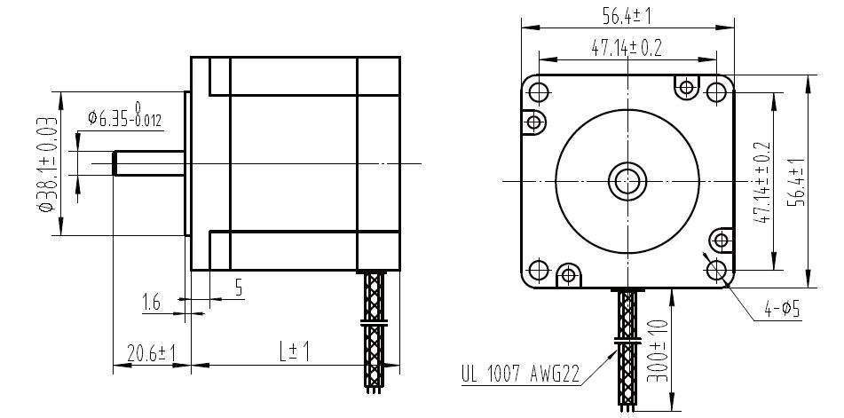
Lead Wire Mode Options:
Shaft Mode can be customized as the requirement.
More Information on detail, please feel free to contact me

AR28 is a high-integrated and compact size stepper driver. It adopts standard RS485 communication protocol, can be connected with PLC, HMI, industrial computer and other upper computer with only two communication lines. Up to 32 axes of motion platform networking can be achieved with its built-in motion control commands.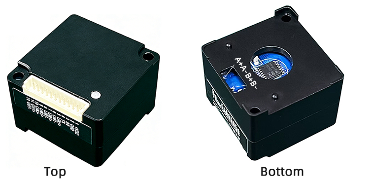
AR28 can be set to 1-256 subdivisions and adopts built-in micro-subdivision technology, which can achieve high subdivision effects even under low subdivision conditions, ensuring that the motor operates with uniform step intervals and no large or small step problems.
Can be set between 1-256 subdivisions, with uniform motor step spacing; Stable output at 1/12 rpm
AR28 is designed for NEMA11/NEMA14 stepper motor, The NEMA11/NEMA14 integrated stepper motor with torque 0.06 ~ 0.35Nm:
1. Electrical Specifications
| Parameter | AR28 (5V IO) | Unit | ||
|---|---|---|---|---|
| Min | Typical | Max | ||
| Continuous Output Current | 0 | — | 1.5 | A |
| Power Supply Voltage (DC) | 15 | 24 | 28 | VDC |
| Control Signal Input Current | 6 | 10 | 16 | mA |
| Overvoltage Protection Voltage | — | 32 | — | VDC |
| Insulation Resistance | 100 | — | — | MΩ |
2. Operating Environment and Parameters
| Parameter | Specification |
|---|---|
| Cooling Method | Natural cooling or forced air cooling |
| Operating Environment - Location | Keep away from heating equipment, dust, oil mist, high humidity & strong vibration. No flammable gas or conductive dust. |
| Operating Environment - Temperature | -5℃ ~ 45℃ |
| Operating Environment - Humidity | 40 ~ 90% RH |
| Operating Environment - Vibration | 10 ~ 55Hz/0.15mm |
| Storage Temperature | -20℃ ~ 65℃ |
| Operating Altitude | ≤1000m |
| Weight | Driver section approx. 50g (excluding motor) |
3. Product Dimensions and Motor Matching
AR28 series closed-loop integrated motor basic parameters:
| Product Model | Motor Holding Torque | Shaft Length L | Motor Length L | Motor Specification |
|---|---|---|---|---|
| AR28-006IE | 0.06 Nm | 20mm | 32mm | NEMA11 |
| AR28-012IE | 0.12 Nm | 20mm | 51mm | NEMA11 |
| AR28-015IE | 0.15 Nm | 24mm | 34mm | NEMA14 |
| AR28-025IE | 0.25 Nm | 24mm | 47mm | NEMA14 |
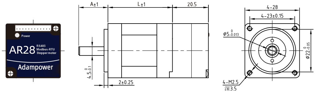
AR28-006IE / AR28-012IE Dimension Drawing (Refer to NEMA11 diagrams)
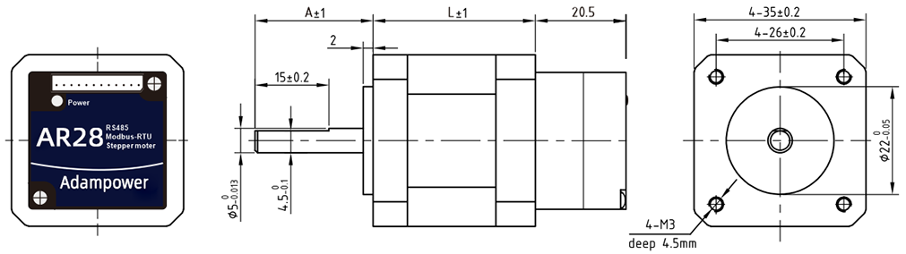
AR28-015IE / AR28-025IE Dimension Drawing (Refer to NEMA14 diagrams)
4. Heat Dissipation Precautions
The reliable operating ambient temperature for closed-loop integrated motors is typically within -5℃ ~ 45℃. Normal operating temperature is 50-80℃. If exceeding 80℃, it is necessary to evaluate whether the operating conditions and integrated motor selection are appropriate. If necessary, install a fan near the driver for forced cooling to ensure the driver operates within the reliable working temperature range.
5. LED Status Indicator
The red LED serves as both power indicator and fault display. When the driver is powered on, the LED is constantly on; when the driver is powered off, the LED is off. When a fault occurs, the indicator flashes in a 5-second cycle; when the fault is cleared by the user, the LED remains constantly on. The number of flashes within 5 seconds represents different fault information, as shown in the following table:
| No. | Flash Count | Fault Description |
|---|---|---|
| 1 | 1 | Overcurrent or inter-phase short circuit fault |
| 2 | 2 | Overvoltage fault |
| 3 | 3 | Undervoltage alarm |
| 4 | 7 | Position deviation alarm (excessive error) |
| 5 | 9 | Driver error, requires maintenance |
| 6 | 4 | Network congestion fault, requires power cycle (flashes 4 times, does not cycle) |
When a fault occurs, the driver will stop and display the corresponding fault code (item 3 network congestion has no code). The user must re-enable the driver or power cycle to clear the fault. When the driver detects a fault, it saves the latest fault to the EEPROM in a queue format. The driver can save up to 10 latest historical faults.
6. OUT Output Port Wiring Diagram
OUT /OUT- ports are differential output ports, allowing maximum voltage of 24V. Port instantaneous output current is 100mA, continuous output current is 50mA. To protect the port, when connecting external brakes, solenoid valves, relays, etc., freewheeling diodes must be connected across the devices to prevent port damage.
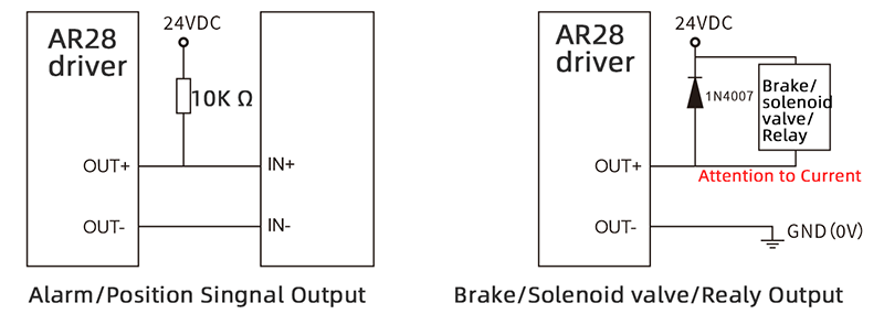
7. Zero-return Function
Zero-return function with two trajectory A and when limit signal is triggered and not:
8. Communication Protocol
Communication uses standard MODBUS protocol, supporting 0x03 (read register), 0x06 (write single register), 0x10 (16) (write multiple registers). Serial communication format: baud rate 9600~115200, 8 data bits, no parity, 1 stop bit.
AR28 Modbus Stepper Motor Controller User Manual
Software Modbus Poll
AdamPower Software
More Information on detail, please feel free to contact me