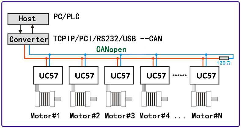
UC42 is a high-integration integrated stepper motor driver launched by adampower(www.adampower.de). It supports CANopen protocol's CiA301 and CiA402 sub-protocols. It can be connected to host computers such as PLCs, industrial computers, and controllers using only two communication wires. Through built-in motion control instructions, a network of up to 100 axes of stepper motors can be realized.
UC42 adopts the latest 32-bit DSP digital chip, possessing advanced drive control algorithms and noise suppression technology, ensuring smooth motor operation, low noise, and controllable temperature. Users can set any ID address within 1-255 and any current value within 0-8A through the host computer.
The UC42 bus-type driver has a maximum output peak current of 2.5A and can drive 42-specification and smaller two-phase open-loop stepper motors. The product is an integrated design that can be combined with a 42 stepper motor to form an integrated unit. UC42 can be set with 1-256 subdivisions and adopts built-in micro-stepping technology. Even under low subdivision conditions, it can achieve high subdivision effects, ensuring uniform motor step distance and no size-step issues.
UC42 has 3 input signal ports and 2 output signal ports, supporting position, speed, and homing control modes with a maximum communication rate of 1Mbps. It is particularly suitable for long-distance multi-axis applications, reducing wiring and enhancing driver reliability.
Mainly used in electronic production equipment, semiconductors, medical instruments, environmental protection equipment, automatic testing equipment, small automatic processing equipment, and other automation equipment with many motor axes and compact space requirements.
| UC42 Parameter | Minimum | Typical | Maximum | Unit |
|---|---|---|---|---|
| Continuous Output Current | 0.1 | - | 2.5 | A |
| Input Power Voltage | 12 | 24 | 36 | VDC |
| Logic Input Current | 2 | 5 | 10 | mA |
| Logic Input Voltage | 5 | 5 | 24 | Vdc |
| Pulse Frequency | 0 | - | 100 | kHz |
| Insulation Resistance | 100 | - | - | MΩ |
| Parameter | Specification |
|---|---|
| Cooling Method | Heat sink cooling |
| Operating Occasion | Keep away from other heating equipment as much as possible; avoid dust, oil mist, corrosive gases, and strong vibration places; combustible gases and conductive dust prohibited. |
| Operating Environment Temperature | 0℃ ~ 50℃ |
| Humidity | 40-90% RH (Non-condensing) |
| Vibration | 10~55Hz/0.15mm |
| Storage Temperature | -20℃ ~ +80℃ |
UC42 driver can be integrated with 42-specification stepper motors. Our company provides 0.35Nm, 0.5Nm, 0.7Nm integrated motor products. If purchasing only the UC42 driver and the equipment has requirements for low-speed vibration, it is recommended to contact us for parameter matching.
Standard Integrated Unit Basic Parameters:
| Product Model | Motor Holding Torque (Nm) | Body Length (mm) | Features |
|---|---|---|---|
| UC42-03 | 0.35 | 40 | 1. Saves wiring; 2. Motor parameters written into control algorithm; |
| UC42-05 | 0.5 | 48 | |
| UC42-07 | 0.7 | 60 |
When installing the driver, please use upright side mounting to create strong air convection on the radiator surface; if necessary, install a fan near the driver for forced cooling to ensure the driver works within a reliable operating temperature range (Driver reliable operating temperature is usually within 60°C, motor operating temperature is within 80°C).
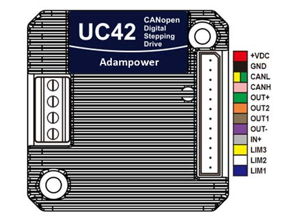
| Port | Pin | Symbol | Name | Function |
|---|---|---|---|---|
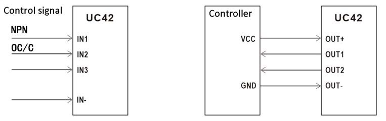
| Input Signal | 1 | IN1 | Input Port, Default Positive Limit | Supports 5/24VDC control signals, limited to NPN, OC, or C-type signal input. Port function supports software modification. |
| 2 | IN2 | Input Port, Default Home | ||
| 3 | IN3 | Input Port, Default Negative Limit | ||
| 4 | IN- | Input Signal Power Negative | Signal power common negative terminal. | |
| Output Signal | 5 | OUT- | Output Signal Power Negative | Common Terminal |
| 6 | OUT1 | Output Signal, Default Alarm | High current output, built-in pull-up resistor and freewheeling diode. | |
| 7 | OUT2 | Output Signal, Default Driver Status | ||
| 8 | OUT+ | Output Signal Power Positive | Common Terminal | |
| Communication | 9 | CANH | Communication Port | CANH Communication Line |
| 10 | CANL | Communication Port | CANL Communication Line | |
| Power | 11 | GND | Power Negative | Power Supply Ground |
| 12 | VDC | Power Positive | Recommended Voltage 24VDC |
| Port | Pin | Symbol | Name | Function |
|---|---|---|---|---|
| Motor Interface | 1 | A+ | Motor Phase Wires | Connect to the A and B windings of a 2-phase hybrid stepper motor according to the motor drawing. Suitable for driving 42 series hybrid stepper motors. |
| 2 | A- | |||
| 3 | B+ | |||
| 4 | B- |
| Port | Fault Type | Flash Count | Function |
|---|---|---|---|
| CN3 | Normal | 0 | No fault, indicator light stays on. |
| Overcurrent | 1 | Overcurrent or phase-to-phase short circuit fault. | |
| Overvoltage | 2 | Overvoltage fault (Voltage > 43VDC). | |
| Hardware Fault | 3 | Hardware fault. | |
| Phase Loss Fault | 4 | Motor open circuit or poor contact fault. | |
| EEPROM Error | 5 | EEPROM error. | |
| Undervoltage Fault | 6 | Undervoltage (Voltage < 9VDC). |
CAN is the abbreviation of Controller Area Network. Originally designed by German BOSCH company for automobile monitoring and control, CAN application has expanded beyond the automotive industry to process industry, mechanical industry, robotics, CNC machine tools, medical equipment, and sensors.
Compared with other buses, the CAN bus has the following characteristics:
The CAN bus communication interface specifies the physical layer and data link layer functions of the CAN protocol but does not specify the application layer. It is incomplete and requires a high-layer protocol to define how to use the 11/29-bit identifier COB-ID and 8-byte data in CAN messages. Therefore, the UC42 driver introduces the CANopen communication protocol.
CANopen protocol is one of the standards defined by CAN-in-Automation (CiA) and gained wide recognition shortly after release. Especially in Europe, CANopen is considered the leading standard in CAN-based industrial systems.
CANopen protocol consists of a series of sub-protocols, divided into communication sub-protocols and device sub-protocols. The communication sub-protocol proposes the concept of Object Dictionary and defines objects and parameters in the communication sub-protocol area. Every CANopen device must at least comply with the communication sub-protocol. Based on the communication sub-protocol, device sub-protocols are expanded according to different industries or device application fields. CiA301 is the most basic communication sub-protocol, standardizing the CANopen network framework and defining communication methods and behavior specifications between different CANopen devices. The UC42 driver supports the CiA 301 communication sub-protocol and the CiA 402 device sub-protocol for drivers.
Object Dictionary
Object Dictionary (OD) is the core concept of CANopen. Every CANopen device in the network has an object dictionary. The object dictionary is an ordered collection of data objects describing all communication and device parameters, located via a 16-bit index and an 8-bit sub-index.
| Operation Type | Command Word Rules |
|---|---|
| Read | The command word for message transmission is always 0x40 |
| If the received data is 1 byte, the received command word is 0x4F. | |
| If the received data is 2 bytes, the received command word is 0x4B. | |
| If the received data is 4 bytes, the received command word is 0x43. | |
| If there is an error in the received data, the received command word is 0x80. | |
| Write | If the data to be sent is 1 byte, the sending command word is 0x2F. |
| If the data to be sent is 2 bytes, the sending command word is 0x2B. | |
| If the data to be sent is 4 bytes, the sending command word is 0x23. | |
| If the message is sent successfully, the received command word is 0x60. | |
| If the message is sent unsuccessfully, the received command word is 0x80. |
Message Format
As an application layer protocol for the CAN bus, CANopen protocol mainly defines the arbitration field (11 bits) and data field (up to 8 bytes) in CAN messages.
In CANopen protocol, the 11-bit arbitration field is divided into the high 4-bit Function Code and the low 7-bit Node-ID, called COB-ID (Communication Object Identifier). The CANopen identifier structure is shown below, where the Node-ID range is 1~127.
CANopen Predefined Master/Slave Connection Set
| Bit 10-7 | Bit 6-0 |
|---|---|
| Function Code | Node-ID |
UC42 driver supports the following types of CANopen messages:
The table below shows the function codes and corresponding COB-IDs for various messages predefined in the communication sub-protocol CiA301.
| Communication Object | Function Code | COB-ID |
|---|---|---|
| NMT | 0000 | 0h |
| SYNC | 0001 | 80h |
| PDO1 (TX) | 0011 | 181h-1FFh |
| PDO1 (RX) | 0100 | 201h-27Fh |
| PDO2 (TX) | 0101 | 281h-2FFh |
| PDO2 (RX) | 0110 | 301h-37Fh |
| PDO3 (TX) | 0111 | 381h-3FFh |
| PDO3 (RX) | 1000 | 401h-47Fh |
| PDO4 (TX) | 1001 | 481h-4FFh |
| PDO4 (RX) | 1010 | 501h-57Fh |
| SDO (TX) | 1011 | 581h-5FFh |
| SDO (RX) | 1100 | 601h-67Fh |
| Heart Beat | 1110 | 701h-77Fh |
Process Data Object (PDO)
SDO protocol is used for object dictionary operations and processing data with low real-time requirements. Data with high real-time requirements is usually transmitted via PDO. PDO communication is based on the Producer/Consumer model, sending data from one device (producer) to another device (consumer) or many other devices (broadcast), and is an unacknowledged transmission mode. Data transmission is limited to 1 to 8 bytes. CANopen devices complete receiving or sending by describing two parameters of PDO: Communication Parameter and Mapping Parameter. UC42 driver supports 4 RPDOs and 4 TPDOs and describes the communication parameters and mapping parameters of each PDO port according to CiA 301 sub-protocol.
Service Data Object (SDO)
SDO messages are mainly used to access the device's object dictionary and configure devices in the CANopen network. SDO communication is based on the Client/Server model, where sent messages must be acknowledged by the receiver. The accessor is called the Client, and the device whose object dictionary is accessed and responds to read/write requests is called the Server. The protocol stipulates that reading the value of an object dictionary is called Upload, while modifying the value of a parameter is called Download. UC42 driver supports both Fast SDO and Normal SDO protocols described in CiA301.
Network Management Object (NMT)
NMT network management is based on a Master/Slave structure. The master station can control the state machine of the slave station via NMT messages. After a CANopen device is powered on or reset, it first enters the Initialization state. After program initialization ends, the device automatically sends a Boot-Up message and then automatically enters the Pre-Operational state. Thereafter, the slave device switches between states according to NMT messages sent by the master station.
Synchronization Object (SYNC)
SYNC provides a reference clock for the network to synchronize devices. SYNC is a Producer/Consumer communication relationship. The SYNC object is sent by one SYNC producer, and all other devices in the network can receive it. If devices in the network support synchronized PDO functionality, SYNC can be used to achieve simultaneous actions of multiple devices. The COB-ID of the SYNC message is 0x80, having a very high priority, ensuring normal SYNC transmission. Also, SYNC messages can contain no data to reduce the data volume of SYNC messages.
Emergency Object (EMCY)
Devices can report internal faults to the CANopen network via the Emergency Object (EMCY). EMCY belongs to the Producer/Consumer communication model, where all devices in the network can consume this message. The EMCY message occupies the full 8 bytes of data. Bytes 0 and 1 are the Error Code, corresponding to various error types. Byte 2 is the Error Register, stored in object dictionary unit 1001h, corresponding to various types of faults in the device. Bytes 3~7 content is the manufacturer-defined error field, which can be specific fault types. Through the EMCY object, the master station can conveniently grasp specific fault situations of the slave station.
The CiA402 protocol defines a standard state machine for motion control devices, as well as various operating modes and their definitions in the object dictionary.
The standard state machine describes the device states and possible control sequences of the driver. Each state represents a specific internal or external behavior, and the device state determines which commands can be received.
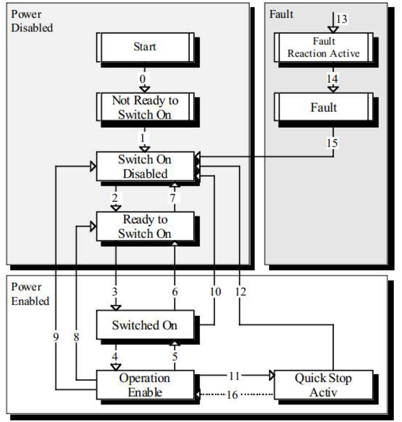
State Descriptions:
| State Name | Description |
|---|---|
| Not Ready to Switch on | Device power is on, driver is initialized, internal self-test is executed, and brake is activated. |
| Switch on Disabled | CANopen communication has started, SDO communication service can be used to set driver parameters. |
| Ready to Switch on | Driver continues parameter setting, motor is not excited. |
| Switched on | Driver motor ready state; output stage voltage is switched on last in this state, but drive function cannot be executed. |
| Operation Enable | Driver motor enabled, driver normal operation state, controls motor according to control mode. |
| Quick Stop Active | Quick stop function is activated, drive function has started, and motor is also started. |
| Fault Reaction Active | Driver detects an alarm occurrence, stops according to set mode, motor still enabled. |
| Fault | Error occurred, allows changing driver parameters. |
The driver state machine is controlled via bits 0~3 and bit 7 of the Control Word (Object 6040h), as described below:
| Command | Bit7 | Bit3 | Bit2 | Bit1 | Bit0 | State Transition |
|---|---|---|---|---|---|---|
| Shutdown | 0 | X | 1 | 1 | 0 | 2, 6, 8 |
| Switch on | 0 | 0 | 1 | 1 | 1 | 3 |
| Switch on + Enable operation | 0 | 1 | 1 | 1 | 1 | 3 + 4 |
| Disable voltage | 0 | X | X | 0 | X | 7, 9, 10, 12 |
| Quick stop | 0 | X | 0 | 1 | X | 7, 10, 11 |
| Disable Operation | 0 | 0 | 1 | 1 | 1 | 5 |
| Enable Operation | 0 | 1 | 1 | 1 | 1 | 4, 16 |
| Fault reset | 0→1 | X | X | X | X | 15 |
The states in the state machine can be displayed via bits 0~3, bit 5, and bit 6 of the Status Word (Object 6041h), as described below:
| State | Bit6 | Bit5 | Bit3 | Bit2 | Bit1 | Bit0 |
|---|---|---|---|---|---|---|
| Not ready to switch on | 0 | X | 0 | 0 | 0 | 0 |
| Switch on disabled | 1 | X | 0 | 0 | 0 | 0 |
| Ready to switch on | 0 | 1 | 0 | 0 | 0 | 1 |
| Switched on | 0 | 1 | 0 | 0 | 1 | 1 |
| Operation enabled | 0 | 1 | 0 | 1 | 1 | 1 |
| Quick stop active | 0 | 0 | 0 | 1 | 1 | 1 |
| Fault reaction active | 0 | X | 1 | 1 | 1 | 1 |
| Fault | 0 | X | 1 | 0 | 0 | 0 |
The start/stop control commands and status description of the driver are mainly implemented through the Control Word 6040h and Status Word 6041h.
Control Word Common Commands:
| Value | Function Description |
|---|---|
| 00 | Initialization Step 0: At this time, 6041 low 4-bit status is 0000, motor released; |
| 06 | Initialization Step 1: At this time, 6041 low 4-bit status is 0001, motor released; |
| 07 | Initialization Step 2: At this time, 6041 low 4-bit status is 0011, motor enabled; |
| 0F | Initialization Step 3: At this time, 6041 low 4-bit status is 0111, motor enabled; |
| 0F | Start command in Speed Mode (6061=3); |
| 0F->1F | Start command in Homing Mode (6061=6); |
| 0F->1F | Absolute motion start command in Position Mode (6061=1); |
| 4F->5F | Relative motion start command in Position Mode (6061=1); |
Status Word Bit Definitions:
| Bit | Definition | Description |
|---|---|---|
| Bit7 | Driver Status | 0: Driver normal; 1: Driver alarm; |
| Bit8 | Homing Status | 0: Homing not complete; 1: Homing complete; |
| Bit11 | Control Word Echo | 0: Indicates Bit4 of 6040h is 0; 1: Indicates Bit4 of 6040h is 1; |
| Bit13 | Motor Status | 0: Motor released; 1: Motor enabled; |
| Bit14 | Motion Status | 0: Motor stopping; 1: Motor running; |
| Bit15 | Position Status | 0: Position mode motion not in position; 1: Position mode motion in position; |
Example: Driver Initialization after Power-on.
| Master Station | Slave Station | Function |
|---|---|---|
| 00: 01 00 | NMT Initialization | NMT Initialization |
| 601: 2B 40 60 00 00 00 00 00 | 581: 60 40 60 00 00 00 00 00 | 6041: xxxx xxxx xxxx 0000 |
| 601: 2B 40 60 00 06 00 00 00 | 581: 60 40 60 00 00 00 00 00 | 6041: xxxx xxxx xxxx 0001 |
| 601: 2B 40 60 00 07 00 00 00 | 581: 60 40 60 00 00 00 00 00 | 6041: xxxx xxxx xxxx 0011 |
| 601: 2B 40 60 00 0F 00 00 00 | 581: 60 40 60 00 00 00 00 00 | 6041: xxxx xxxx xxxx 0111 |
CANopen sets the driver operating mode through Object 6060h (Mode of Operation) and reflects the current operating mode status through Object 6061h (Mode of operation display). UC42 currently supports 3 operating modes: Profile Position Mode, Profile Velocity Mode, Homing Mode.
| Index | SubIndex | Name | Type | Attr | PDO Map | Range | Default |
|---|---|---|---|---|---|---|---|
| 6060h | 00 | Operating Mode | I8 | RW | YES | 0: Undefined; 1: Position; 3: Velocity; 6: Homing | 0 |
Work Process Description
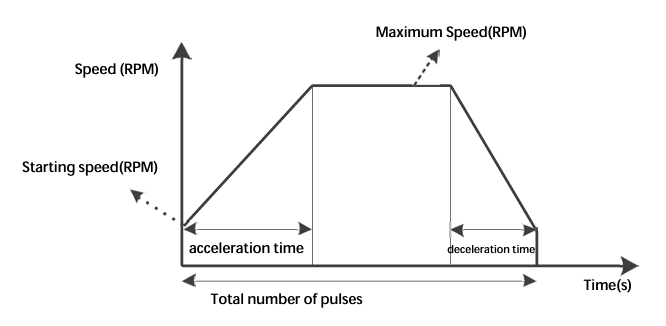
Position mode uses a trapezoidal acceleration/deceleration curve. Users can achieve precise position control by setting the Starting Speed (200E0010h), Maximum Speed (60810020h), Acceleration Time (60830020h), Deceleration Time (60840020h), and Total Pulses (607A0020h) via the bus.
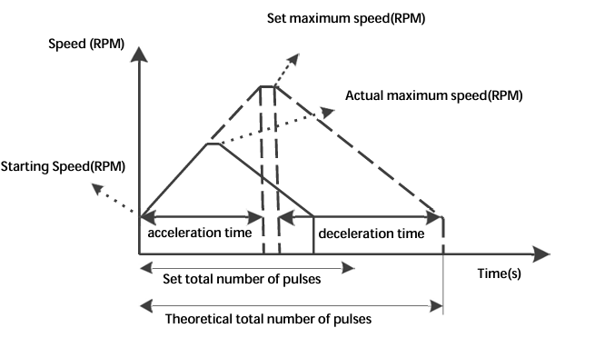
When the user-set total pulse count is small, the motor may need to decelerate before accelerating to maximum speed. The actual running curve is the solid line.
Relevant Object Dictionary Content:
| Index | SubIndex | Name | Type | Attr | Range | Unit |
|---|---|---|---|---|---|---|
| 6060h | 00 | Operating Mode | I8 | RW | 0, 1, 3, 6 | - |
| 607Ah | 00 | Total Pulses | I32 | RW | -1000000~1000000 | Pulses |
| 6081h | 00 | Max Speed | U32 | RW | 5-3000 | r/min |
| 6083h | 00 | Accel Time | U32 | RW | 1-2000 | rps/s |
| 6084h | 00 | Decel Time | U32 | RW | 1-2000 | rps/s |
Control Word and Status Word in Position Mode
| Bit | Name | Value | Description |
|---|---|---|---|
| Bit4 | New set-point | 0 | No target position assumed |
| 1 | Target position assumed | ||
| Bit5 | Change set immediately | 0 | Complete current position then start next |
| 1 | Interrupt current position and start next | ||
| Bit6 | abs/rel | 0 | Target position is an absolute value |
| 1 | Target position is a relative value | ||
| Bit8 | Halt | 0 | Terminate current position |
| 1 | Decelerate to stop using set deceleration |
Status Word Bits 10 and 15:
| Bit | Name | Value | Description |
|---|---|---|---|
| Bit10 | Target reached | 0 | Halt=0: Target not reached; Halt=1: Axis decelerating; |
| 1 | Halt=0: Target reached; Halt=1: Axis speed is 0; | ||
| Bit12 | Set-point acknowledge | 0 | Target position pending |
| 1 | Target position effective | ||
| Bit15 | Pend | 0 | Not in position |
| 1 | In position |
Example: Relative motion with Accel 100ms, Decel 100ms, Max Speed 60r/min, Total Pulses 5000.
| Master | Slave | Function |
|---|---|---|
| 601: 2B 40 60 00 00 00 00 00 | ... | Initialize Servo State Machine |
| 601: 23 83 60 00 64 00 00 00 | ... | Set Accel Time 100 |
| 601: 23 84 60 00 64 00 00 00 | ... | Set Decel Time 100 |
| 601: 23 81 60 00 3C 00 00 00 | ... | Set Max Speed 60 |
| 601: 23 7A 60 00 88 13 00 00 | ... | Set Pulses 5000 |
| 601: 2F 60 60 00 01 00 00 00 | ... | Switch to Position Mode |
| 601: 2B 40 60 00 4F 00 00 00 | ... | Send Relative Motion Command 1 |
| 601: 2B 40 60 00 5F 00 00 00 | ... | Send Relative Motion Command 2 |
Work Process Description
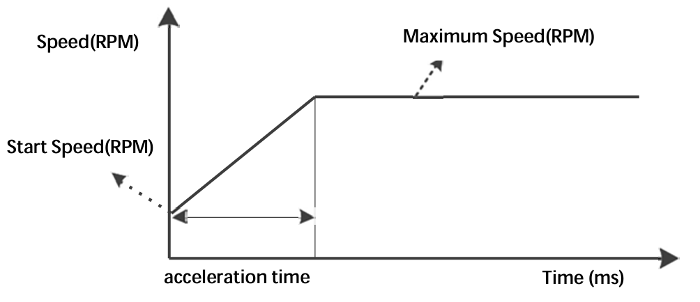
The acceleration curve for velocity mode is shown below. Unlike position mode, velocity mode only requires setting Starting Speed (200E00h), Maximum Speed (60FF00h), and Acceleration Time (608300h).
| Index | SubIndex | Name | Type | Attr | Range |
|---|---|---|---|---|---|
| 6060h | 00 | Operating Mode | I8 | RW | 0, 1, 3, 6 |
| 60FFh | 00 | Max Speed | I32 | RW | -1000~1000 r/min |
| 6083h | 00 | Accel Time | U32 | RW | 1-2000 rps/s |
| 6084h | 00 | Decel Time | U32 | RW | 1-2000 rps/s |
Control Word and Status Word
| Bit | Name | Value | Description |
|---|---|---|---|
| Bit8 | Halt | 0 | Execute motion |
| 1 | Stop motion |
Example: Rotation with Accel 100ms, Decel 100ms, Max Speed 60r/min.
| Master | Slave | Function |
|---|---|---|
| 601: 2F 60 60 00 03 00 00 00 | ... | Switch to Velocity Mode |
| 601: 2B 40 60 00 06 00 00 00 | ... | State Machine Transition |
| 601: 2B 40 60 00 0F 00 00 00 | ... | Enable Operation |
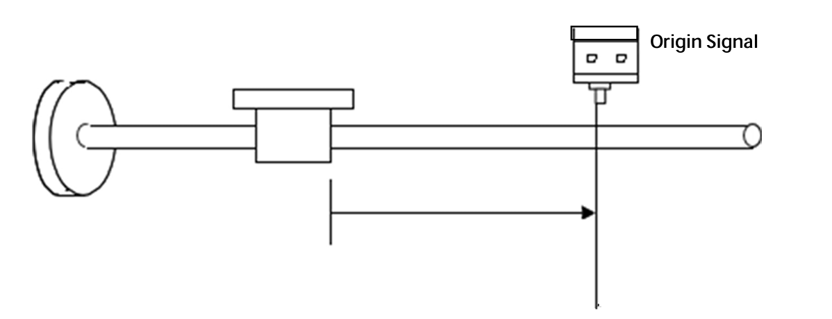
Work Process Description
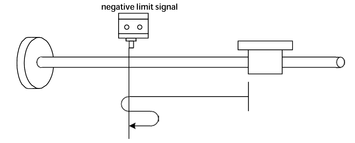
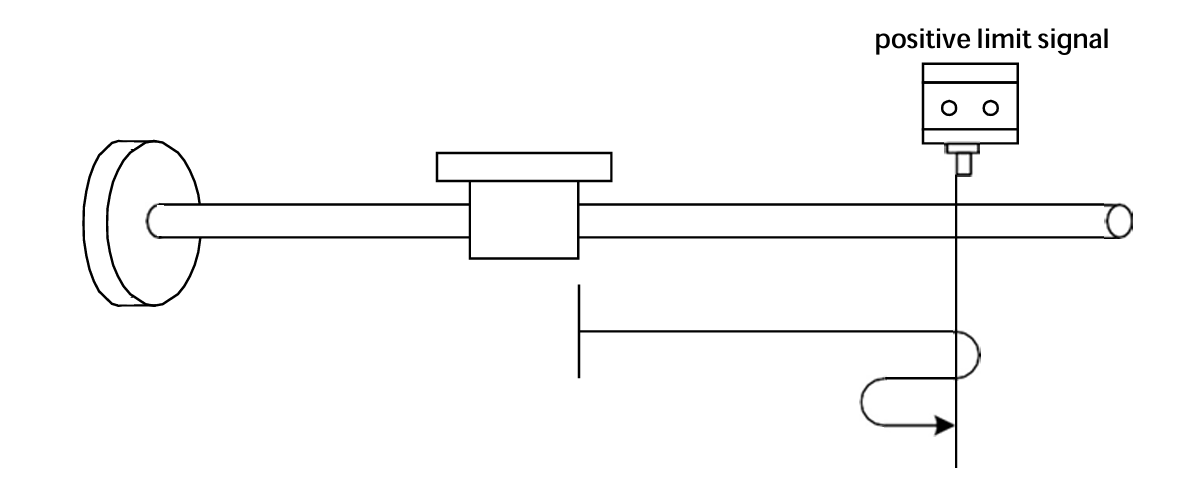
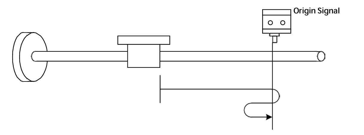
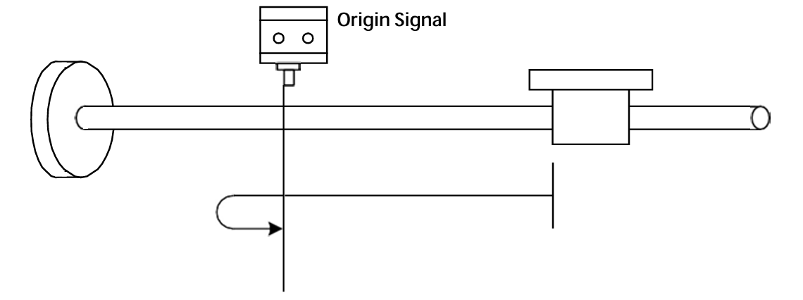
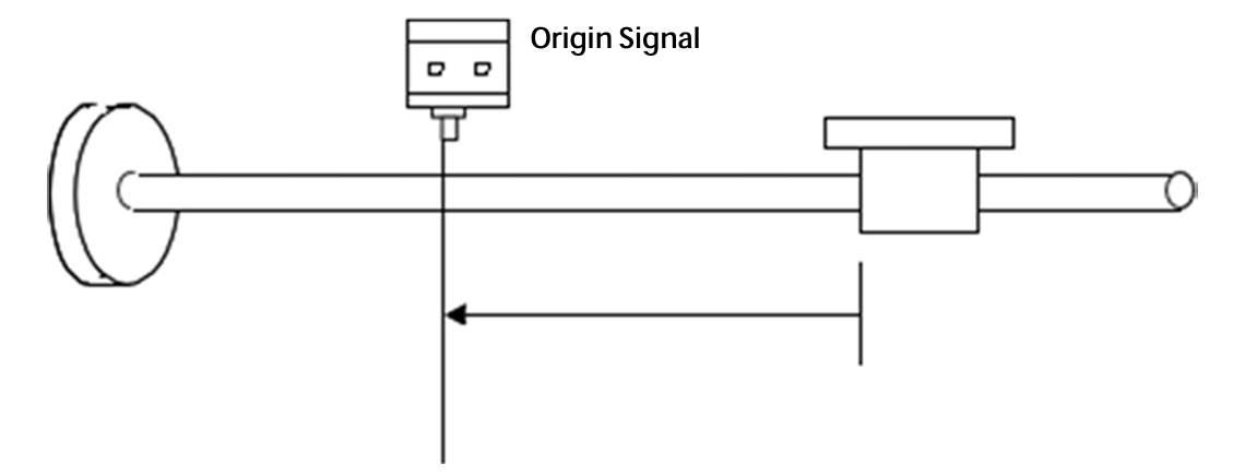
In Homing mode, the home signal must be connected to the driver input. The driver internally completes the search and positioning of the mechanical home. Set Object 6060h to 6.
Relevant Object Dictionary:
| Index | SubIndex | Name | Type | Range |
|---|---|---|---|---|
| 6060h | 00 | Operating Mode | I8 | 6 |
| 6098h | 00 | Homing Mode | U8 | 17, 18, 24, 29, 41, 42 |
| 6099h | 01 | Homming Speed Fast | U32 | 0-1000 r/min |
| 6099h | 02 | Homing Speed Slow | U32 | 0-1000 r/min |
| 609Ah | 00 | Homing Accel/Decel | U32 | 1-2000 rps/s |
| 607Ch | 00 | Home Offset | I32 | -0x7FFFFFFF~0x7FFFFFFF |
Currently supported Homing Modes:
Control Word and Status Word
| Bit | Name | Value | Description |
|---|---|---|---|
| Bit4 | Homing operation start | 0 | Homing mode inactive |
| 0→1 | Start homing mode | ||
| 1 | Homing mode active | ||
| 1→0 | Interrupt homing mode | ||
| Bit8 | Halt | 0 | Execute bit4 command |
| 1 | Stop axis using homing acceleration |
UC42 parameters include CiA301 (1000h~1FFF), Manufacturer Defined (2000h~2FFF), and CiA402 (6000h~6FFF).
| Index | Name | Type | Attr | Description | Default |
|---|---|---|---|---|---|
| 2000H | Driver Node ID | U16 | RO | Set via 0x2008 | - |
| 2001H | Motor Status Register | U16 | RO | 0: Static; 1: Running | 0 |
| 2003H | Input Signal Status | U16 | RO | Bit0~Bit2: IN1~IN3 level | 0 |
| 2004H | Output Signal Status | U16 | RO | Bit0~Bit1: OUT1~OUT2 status | 0 |
| 2005H | Current Setting | U16 | RW/S | 1~25 (*0.1A RMS) | 15 |
| 2006H | Subdivision Setting | U16 | RW/S | See table below | 13 |
| 2007H | Lock Current | U16 | RW/S | 0: Auto half-current; 1: Full current | 0 |
| 2008H | Custom Node ID | U16 | RW/S | 1~127 | 1 |
| 2009H | Baud Rate Setting | U16 | RW/S | 0:50k; 1:100k; 2:125k; 3:250k; 4:500k; 5:1000k | 2 |
| 200AH | Limit Stop Mode | U16 | RW/S | 0: Stop; 1: E-Stop; 2: Invalid | 0 |
| 200BH | Control Mode Select | U16 | RW/S | 0: Bus Control | 0 |
| 200CH | EEPROM Update | U16 | RW | 0: Update RW params to EEPROM; 1: Do not update | 1 |
| 200EH | Start Speed | U16 | RW | 0-1000 r/min | 10 |
| 200FH | Motor Enable/Release | U16 | RW | 0: Release; 1: Enable; 2: Invalid | 2 |
| 2010H | Parameter Reset | U16 | RW | 0: Invalid; 1: Factory Reset; 2: Save all RW params | 0 |
| 2011h | Fault Reset Command | U16 | RW | 0: Invalid; 1: Reset | 0 |
| 2012h | Current Pos Clear | U16 | RW | 1: Clear current position | 0 |
| 2030h | Input Terminal Config | U16 | RW/S | Bit0-2: IN1-IN3 valid level (0:Default, 1:Invert) | 0 |
| 203Ch | Output Terminal Config | U16 | RW/S | Bit0-1: OUT1-OUT2 valid level (0:Default, 1:Invert) | 0 |
| 2040H | Current Loop Kp | U16 | RW/S | Unit: 0.1% | 220 |
| 2041H | Current Loop Ki | U16 | RW/S | Unit: 0.1% | 3 |
Subdivision Values (2006H):
| 0: 200 | 5: 6400 | 10: 4000 |
| 1: 400 | 6: 12800 | 11: 5000 |
| 2: 800 | 7: 25600 | 12: 8000 |
| 3: 1600 | 8: 1000 | 13: 10000 |
| 4: 3200 | 9: 2000 | 14: 20000 |
| Index | Name | Type | Attr | Description | Default |
|---|---|---|---|---|---|
| 603Fh | Error Code | U16 | RO | Bit0: Overcurrent; Bit1: Overvolt; Bit2: Op-amp; Bit3: Phase loss; Bit4: EEPROM; Bit5: Undervolt | 0 |
| 6040h | Control Word | U16 | RW | Control Word | 0 |
| 6041h | Status Word | U16 | RO | Status Word | 0 |
| 605Dh | Halt Option Code | I16 | RW | 0: Normal stop; 1: E-stop | 0 |
| 6060h | Operating Mode | I8 | RW | 1: Position; 3: Velocity; 6: Homing | 0 |
| 6061h | Operating Mode Display | I8 | RO | Displays current mode | 0 |
| 6064h | Actual Position | I32 | RO | Unit: P | 0 |
| 606Ch | Current Velocity | I32 | RO | Unit: RPM | 0 |
| 607Ah | Target Position | I32 | RW | Total pulses for PP mode | 5000 |
| 607Ch | Home Offset | I32 | RW | Range: -1000000~1000000 | 0 |
| 6081h | Max Speed (PP) | U32 | RW | 5-1000 RPM | 60 |
| 6083h | Acceleration Time | U32 | RW | 1-2000 rps/s | 50 |
| 6084h | Deceleration Time | U32 | RW | 1-2000 rps/s | 50 |
| 6098h | Homing Mode | U8 | RW | Methods 17, 18, 24, 29, 41, 42 | 0 |
| 6099h/01 | Homming Speed Fast | U32 | RW | 1-1000 RPM | 120 |
| 6099h/02 | Homing Speed Slow | U32 | RW | 1-1000 RPM | 60 |
| 609Ah | Homing Accel/Decel | U32 | RW | 1-2000 rps/s | 50 |
| 60FDh | Input Terminal Status | U32 | RO | Bit0: Neg Limit; Bit1: Pos Limit; Bit2: Home | 0 |
| 60FFh | Max Speed (PV) | I32 | RW | Range: -1000~1000 RPM | 120 |
UC42 driver has 6 types of alarm information. After an alarm, the indicator light flashes according to the code.
| Code | Fault Info | Indicator | Reset |
|---|---|---|---|
| Err1: 0x01 | Overcurrent or Phase Short | Flashes 1 time | Lock/Power Reset |
| Err2: 0x02 | Overvoltage (>60VDC) | Flashes 2 times | Lock/Auto Recover |
| Err3: 0x03 | Hardware Fault | Flashes 3 times | Lock/Power Reset |
| Err4: 0x04 | Motor Open Circuit | Flashes 4 times | Lock/Power Reset |
| Err5: 0x05 | EEPROM Error | Flashes 5 times | Lock/Power Reset |
| Err6: 0x06 | Undervoltage | Flashes 6 times | Lock/Auto Reset |
For controllers that do not have built-in CiA402 libraries but support CANopen communication, users need to write function blocks. Below are common functions.
Function List:
| Function Name | INPUT | OUTPUT | Description |
|---|---|---|---|
| MC_POWER | 6040h | 6041h | Driver Enable |
| MC_RESET | 6040h | - | Driver Reset |
| MC_STOP | 6040h | - | Stop Command |
| MC_HOME | 6040h, 6060h, 6098h... | 6041h | Homing Command |
| MC_MOVABS | 6040h, 6060h, 607Ah... | 6041h | Absolute Positioning |
| MC_MOVREL | 6040h, 6060h, 607Ah... | 6041h | Relative Positioning |
| MC_MOVVEL | 6040h, 6060h, 60FFh... | 6041h | Velocity Motion |
| MC_JOG | 6040h, 6060h, 60FFh... | 6041h | JOG Motion |
MC_POWER (Enable):
MC_RESET:
MC_MOVABS (Absolute Position):
| Phenomenon | Possible Problem | Solution |
|---|---|---|
| Motor not rotating | Power not on; Enable not active; Current too low; Protection active; wiring error. | Check power; Check enable signal; Check current setting; Re-power; Check wiring. |
| Inaccurate Position | Signal interference; Grounding issue; Motor wire open; Subdivision error. | Eliminate interference; Reliable grounding; Check wiring; Correct subdivision. |
| Stalling during acceleration | Accel time too short; Torque too low; Voltage too low. | Increase accel time; Reduce load or change motor; Increase voltage. |
1) Advantages of subdivision drivers?
2) Why does the motor only run in one direction?
Our company provides a one-year warranty from the date of shipment for material and process defects in our products. During the warranty period, we provide free repair services for defective products.
Please contact our company's sales representative.
The warranty scope of our products is limited to the device and workmanship (i.e., consistency). We do not guarantee that our products are suitable for the customer's specific application, as suitability depends on the technical requirements, operating conditions, and environment of that application.