Thank you for using our open-loop step drive.
Before using this product, please read this manual carefully to understand the necessary safety information, precautions, and operation methods. Incorrect operation can have extremely serious consequences.
This product is designed and manufactured without the ability to protect personal safety from mechanical system threats. Users are advised to consider safety precautions during mechanical system design and manufacturing to prevent accidents caused by improper operation or product abnormalities.
Due to product improvements, the contents of this manual are subject to change without notice. Our company will not be responsible for any modification of the product by the user.
This product has passed the national mandatory 3C certification, CE certification, ROHS certification.
IRO23 is a newly introduced digital integrated RS485 control drive motor. The driver is designed with 32-bit DSP digital processing technology, variable current technology, low heating technology, and more. It features low vibration, smooth running, low heating, high reliability, and other advantages.
Users can control the drive motor through RS485, which can meet the application needs of most occasions. Low, medium, and high-speed operation are very smooth, with ultra-low noise.
The driver internally integrates a power-on auto-adaptive motor function, which can automatically generate optimal operating parameters for different motors, maximizing the motor's performance.
Suitable for a variety of small and medium-sized automatic equipment and instruments, such as: Engraving Machine, marking machine, cutting machine, medical equipment, laser phototypesetting, plotter, CNC machine tools, automatic assembly equipment.
Ideal for applications where the user expects low noise, low vibration, low heat, and high speed.
| Explanation | IRO23 | |||
|---|---|---|---|---|
| Minimum Value | Typical Value | Maximal Value | Unit | |
| Continuous output current | 0.5 | - | 5.6 | A |
| Power Supply Voltage (DC) | 15 | 24/36 | 50 | VDC |
| Control signal input current | 6 | 10 | 16 | mA |
| Control signal input Voltage | - | 5 | - | VDC |
| Overvoltage point | 54 | 55 | 56 | VDC |
| Step frequency | 1 | - | 1000 | KHz |
| Insulation Resistance | 100 | - | - | MΩ |
The integrated driver can be used for 57 open-loop hybrid stepper motors and linear screw stepper motors of different specifications from major motor manufacturers. The driver can be sold separately.
If you need to purchase our driver and motor complete set of products, we generally recommend the following two standard models. Other models of stepper motors or suitable screw stepper motors can be customized according to customer needs.
| Model No. | Holding Torque (N.m) | Motor Length (mm) | Driver Thickness (mm) | Weight (kg) |
|---|---|---|---|---|
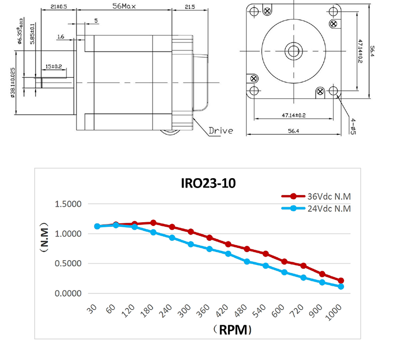
| IRO23-10 | 1.0 | 56±1 | 21.5±1 | 0.9 |
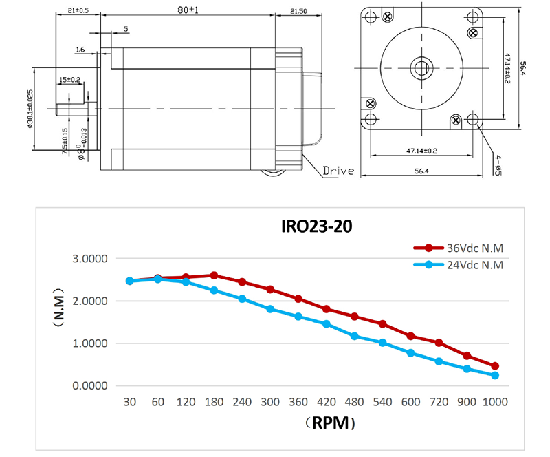
| IRO23-20 | 2.0 | 80±1 | 21.5±1 | 1.2 |
| Cooling Mode | Natural Cooling or forced air cooling |
|---|---|
| Service Environment - Occasion | Cannot be placed next to other heating equipment. Avoid dust, oil mist, corrosive gases, high humidity, and strong vibration sites. Combustible gases and conductive dust are prohibited. |
| Temperature | -10℃ ~ +50℃ |
| Humidity | 40 ~ 90% RH |
| Vibration | 5.9 m/s² MAX |
| Storage temperature | -20℃ ~ 60℃ |
| Use Elevation | Below 1000 meters |
| Weight | 0.7 KG |
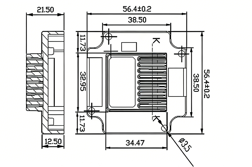
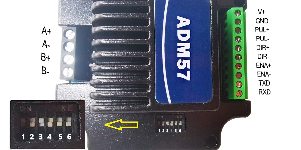
IRO23 RS485 stepper motor driver dimensions:
IRO23-10 RS485 integrated stepper motor specifications and motor torque-frequency characteristic curve:
IRO23-20 RS485 integrated stepper motor specifications and motor torque-frequency characteristic curve:
The reliable operating temperature of the driver is usually within 60℃, and the motor operating temperature is within 80℃.
It is recommended to use the automatic semi-flow mode when using the motor. When the motor stops, the current is automatically reduced by half to reduce the heat of the motor and the drive.
Install the drive with vertical side mounting so that the heat dissipating teeth form strong air convection.
Install a fan near the drive when necessary to force heat dissipation to ensure that the drive works within a reliable operating temperature range.
The green LED is the power indicator. When the driver is connected to power, the LED is constantly bright; when the driver cuts off power or a failure occurs, the LED is extinguished.
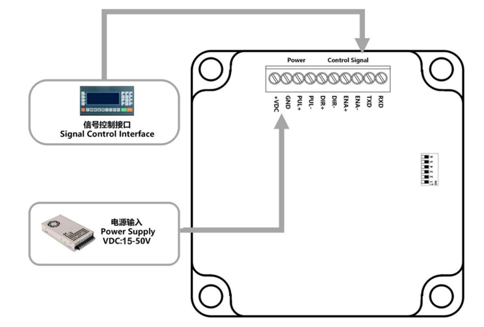
Control Signal Interface:
The control signal and the power supply input port use the 8Pin 2.0 mm terminal.
| Pin Number | Signal Name | Function Description |
|---|---|---|
| 1 | VDC | Power positive input: DC VOLTAGE 15-50VDC |
| 2 | GND | Negative power input: GND of DC voltage |
| 3 | PUL+ | Receiving level 5VDC, pulse control signal input (negative) (left limit) |
| 4 | PUL- | - |
| 5 | DIR+ | Receiving level 5VDC, direction control signal input (negative) (back to zero) |
| 6 | DIR- | - |
| 7 | ENA+ | Receiving level 5VDC, enable control signal input (negative) (right limit) |
| 8 | ENA- | - |
| 9 | TXD | Serial port RS485 TXD |
| 10 | RXD | RXD serial port RS485 |
Motor Interface:
4 Pin 3.5 mm terminal is used as motor connection port.
| Pin Number | Signal Name | Function Description |
|---|---|---|
| 1 | A+ | Two-phase stepping motor A+ phase |
| 2 | A- | Two-phase stepping motor A- phase |
| 3 | B+ | Two-phase stepping motor B+ phase |
| 4 | B- | Two-phase stepping motor B- phase |
The power supply voltage can work normally between the specified ranges. The driver is preferably powered by an unregulated DC power supply, or a transformer buck + bridge rectifier + capacitor filter. Note, however, that the peak voltage ripple after rectification should not exceed its specified maximum voltage. It is recommended that the user supply power with a DC voltage lower than the maximum voltage to prevent the grid from fluctuating beyond the operating range of the driver voltage.
If using a regulated switching power supply, be aware that the output current range of the switching power supply must be set to maximum.
The IRO23 RS485 Stepper Motor Driver uses a 6-bit dial switch to set the address and Baud rate. The details are as follows:
| Baud Rate | SW5 | SW6 |
|---|---|---|
| 9600 | on | on |
| 19200 | off | on |
| 38400 | on | off |
| 57600 | off | off |
Baud rate can be customized according to customer needs. If custom, factory SW5 and SW6 status are ON for the custom baud rate.
| ID | SW1 | SW2 | SW3 | SW4 |
|---|---|---|---|---|
| Reserved (Broadcast address) | on | on | on | on |
| 1 | off | on | on | on |
| 2 | on | off | on | on |
| 3 | off | off | on | on |
| 4 | on | on | off | on |
| 5 | off | on | off | on |
| 6 | on | off | off | on |
| 7 | off | off | off | on |
| 8 | on | on | on | off |
| 9 | off | on | on | off |
| 10 | on | off | on | off |
| 11 | off | off | on | off |
| 12 | on | on | off | off |
| 13 | off | on | off | off |
| 14 | on | off | off | off |
| 15 | off | off | off | off |
Built-in trapezoidal acceleration and deceleration curve generator. Trapezoidal acceleration and deceleration can be performed. Fixed-length operation, continuous operation, deceleration stop, and immediate stop can be realized through communication commands.
Internal operation supports absolute position mode and relative position mode control. Built-in common return to zero function simplifies development.
The internal pulse generator uses 32-bit speed, acceleration, and travel, enabling a wide range of trajectory generation.
Communication uses standard MODBUS protocol, supporting 0x03 (read register), 0x06 (write single register), 0x10 (16) (write multiple registers).
Serial communication format: Baud rate 9600~115200, 8 data bits, no parity, 1 stop bit.
| Address | Parameter Name | Attr | Default | Value Range | Register Description |
|---|---|---|---|---|---|
| 0 | Peak Current | R/W/S | 5000 | 1~6000 | Unit: mA |
| 1 | Subdivision (Pulses per rev) | R/W/S | 6000 | 200~51200 | Pulses required for one motor revolution. |
| 2 | Standby Time | R/W/S | 300 | 100~10000 | Time for driver to enter standby, Unit: ms |
| 3 | Standby Current Percentage | R/W/S | 50 | 0~100 | Unit: % |
| 4 | Dial Status | R | - | - | - |
| 10 | Filter Time | R/W/S | 4000 | 50~25600 | Set filter time of filter: μs |
| 15 | Current Loop Kp | R/W/S | 1000 | 10~32767 | Read-only when auto-tuning is enabled; User writable when disabled. |
| 16 | Current Loop Ki | R/W/S | 200 | 0~32767 | Read-only when auto-tuning is enabled; User writable when disabled. |
| 18 | Baud Rate Selection | R/W/S | 96 | 96~1152 | 96 represents 9600 |
| 22 | RMS Current | R/W/S | 3500 | 1~4200 | Unit: mA |
| 31 | Device ID | R | - | - | - |
| 39 | Total Pulse Count L | R | - | - | External pulses received, Low 16 bits |
| 40 | Total Pulse Count H | R/W | - | - | External pulses received, High 16 bits. Write: Write 1 to clear counter. |
| 48 | Bus Voltage | R | - | - | Return bus voltage, Unit: 0.1V |
| 51 | Motor Running Direction | R/W/S | 1 | 0/1 | 0: Motor direction unchanged; 1: Motor direction reversed. |
| 60 | Return to Zero Speed | R/W/S | 200 | 0~65535 | Unit: pulse/s |
| 62 | Deceleration Low 16bit | R/W/S | 3200 | 0~65535 | Unit: pulse/s² |
| 63 | Deceleration High 16bit | R/W/S | 0 | 0~65535 | Unit: pulse/s² |
| 64 | Speed Low 16bit | R/W/S | 1600 | 0~65535 | Unit: pulse/s |
| 65 | Speed High 16bit | R/W/S | 0 | 0~65535 | Unit: pulse/s |
| 66 | Acceleration Low 16bit | R/W/S | 3200 | 0~65535 | Unit: pulse/s² |
| 67 | Acceleration High 16bit | R/W/S | 0 | 0~65535 | Unit: pulse/s² |
| 68 | Travel Low 16bit | R/W/S | 1600 | 0~65535 | Unit: pulse |
| 69 | Travel High 16bit | R/W/S | 0 | 0~65535 | Unit: pulse |
| 70 | Motion Command | R/W | 0 | 0~5 | Trigger corresponding motion, then address becomes 6. 0 — Deceleration stop 1 — Forward fixed-length motion 2 — Reverse fixed-length motion 3 — Forward continuous motion 4 — Reverse continuous motion 5 — Immediate stop 6 — Default value, meaningless |
| 71 | Return to Zero Command | R/W | 0 | 0~2 | 0 — Exit return to zero 1 — Return to zero with forward limit signal as zero 2 — Return to zero with negative limit signal as zero |
| 72 | Fixed-length Motion Mode | R/W | 0 | 0/1 | 0: Incremental mode 1: Absolute mode |
| 73 | Device Control Register | R/W/S | - | - | See 6.2.1 for specific bit definitions. |
| 74 | Return to Zero Limit Filter Time | R/W/S | 10 | 0~65535 | 1 represents 50μs |
| 75 | Device Status Register | R | - | - | See 6.2.2 for specific bit definitions. |
| 90 | Save Parameters | R/W | 0 | 0/1 | Read address: Return 0: Save not complete; Return 1: Save complete. |
| 91 | Restore Factory Default Parameters | R/W | 0 | 0/1 | Write 1 to start clearing; Read address: Return 0: Clearing not complete; Return 1: Clearing complete. |
| 92~150 | Reserved | R | - | - | Reserved |
| Bit | Name | Default | Description |
|---|---|---|---|
| 7~15 | Reserved | 0 | None |
| 6 | IO Trigger Motion Enable (Default IN1 is trigger port) | 0 | 0 — Trigger port has no function 1 — Trigger port can trigger motion |
| 2~5 | Reserved | 0 | None |
| 1 | Negative Limit Signal Level (Default IN3 is negative limit) | 1 | 0 — Negative limit occurs when optocoupler is OFF 1 — Negative limit occurs when optocoupler is ON |
| 0 | Positive Limit Signal Level (Default IN2 is positive limit) | 1 | 0 — Positive limit occurs when optocoupler is OFF 1 — Positive limit occurs when optocoupler is ON |
| Bit | Name | Default | Description |
|---|---|---|---|
| 8~15 | Reserved | 0 | Reserved |
| 7 | Motion Complete | 1 | 1 — Internal pulse transmission complete 0 — Internal pulse transmission incomplete |
| 6 | Reserved | 0 | 0 |
| 5 | Negative Limit | 0 | 0 — No negative limit signal 1 — Negative limit signal present |
| 4 | Positive Limit | 0 | 0 — No positive limit signal 1 — Positive limit signal present |
| 2~3 | Reserved | 0 | - |
| 1 | Overvoltage | 0 | 0 — No overvoltage 1 — Overvoltage occurred |
| 0 | Overcurrent | 0 | 0 — No overcurrent 1 — Overcurrent occurred |
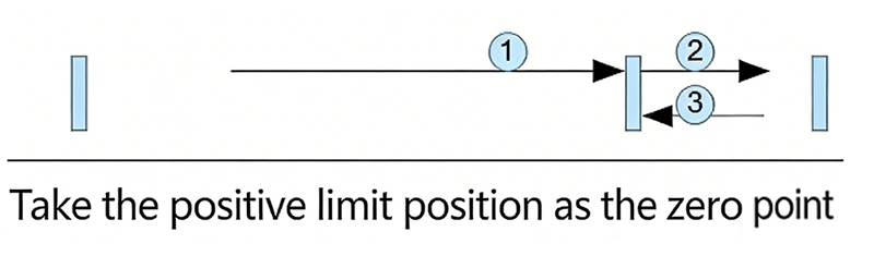
After writing "1" to register address 71 (Return to Zero Command), the process is as follows:
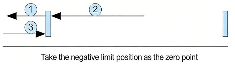
After writing "2" to register address 71 (Return to Zero Command), the process is as follows:
After writing "0" to register address 71 (Return to Zero Command), the driver exits the return to zero process and decelerates to stop.
After completing return to zero, the customer can clear the pulse counter by writing 1 to register address 40 as needed (e.g., in absolute position mode).
Master -> Slave Data:
| Device Addr | Func Code | Register Addr | Read Count | CRC Check | |||
|---|---|---|---|---|---|---|---|
| 01 | 03 | 00 | 00 | 00 | 01 | 85 | 0A |
Slave -> Master Data:
| Device Addr | Func Code | Byte Count | Register Data | CRC Check | ||
|---|---|---|---|---|---|---|
| 01 | 03 | 02 | 0A | 8C | BF | 41 |
Read the stepper motor driver's current value (Register Address 00) as 2700(0xA8C)mA, 2.7A
Master -> Slave Data:
| Device Addr | Func Code | Register Addr | Write Data | CRC Check | |||
|---|---|---|---|---|---|---|---|
| 01 | 06 | 00 | 40 | 06 | 40 | 8A | 4E |
Slave -> Master Data:
| Device Addr | Func Code | Register Addr | Write Data | CRC Check | |||
|---|---|---|---|---|---|---|---|
| 01 | 06 | 00 | 40 | 06 | 40 | 8A | 4E |
Writes 1600(0x640) pulse/s to the stepper motor's Speed Low 16bit (Register Address 64).
Master -> Slave Data:
| Device Addr | Func Code | Start Addr | Write Count | Bytes | Data 1 | Data 2 | CRC | |||||
|---|---|---|---|---|---|---|---|---|---|---|---|---|
| 01 | 10 | 00 | 44 | 00 | 02 | 04 | 38 | 80 | 00 | 01 | 3B | 24 |
Slave -> Master Data:
| Device Addr | Func Code | Start Addr | Write Count | CRC Check | |||
|---|---|---|---|---|---|---|---|
| 01 | 10 | 00 | 44 | 00 | 02 | 01 | DD |
Writes 14464 to the stepper motor's Travel Low 16bit (Register Address 68) and 1 to Travel High 16bit (Register Address 69), meaning total travel is 80000 (0x13880)pulses.
The following example calculates CRC using C language:
Uint16 Funct_CRC16(unsigned char *puchMsg, Uint16 DataLen)
{
    Uint16 i, j, tmp;
    Uint16 crcdata = 0xFFFF;
    for(i = 0; i < DataLen; i++) {
        crcdata = (*puchMsg) ^ crcdata;
        puchMsg++;
        for(j = 0; j < 8; j++) {
            tmp = crcdata & 0x0001;
            crcdata = crcdata >> 1;
            if(tmp) {
                crcdata = crcdata ^ 0xA001;
            }
        }
    }
    return crcdata;
}
Please keep the packing box for transportation, storage, or return to the company for maintenance.
Damage caused by the product itself within one year of using this drive is covered by the warranty.
Add Whatsapp or call:
M.T.: +86 156 5677 5078
Email: SIMON@STEPPING-MOTOR.CN