This stepper motor driver is a driver module designed specifically for two-phase four-wire stepper motors. It realizes motor enable control, direction control, stepping drive, and power supply functions. It is suitable for small automation equipment, 3D printers, numerical control devices, and other scenarios.
| Pin Label | Function Description | Wiring Object |
|---|---|---|
| A+ | Stepper Motor Phase A Positive Terminal | Stepper Motor Phase A Coil Positive Electrode |
| A- | Stepper Motor Phase A Negative Terminal | Stepper Motor Phase A Coil Negative Electrode |
| B+ | Stepper Motor Phase B Positive Terminal | Stepper Motor Phase B Coil Positive Electrode |
| B- | Stepper Motor Phase B Negative Terminal | Stepper Motor Phase B Coil Negative Electrode |
| Pin Label | Function Description | Wiring Object | Electrical Characteristics |
|---|---|---|---|
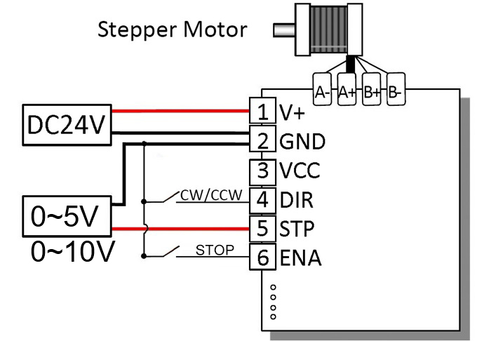
| 24V | 24V DC Power Positive Input | External 24V DC Power Positive Electrode | Rated Input Voltage: DC 24V (9-30V) Typical Value: 24V |
| GND | Power Ground / Signal Ground | External Power Negative Electrode, Control Signal Ground | - |
| VCC | Switch to Low Speed | Floating: High Speed; GND: Low Speed | Vmax = 5.5V, Vmin = 2.1V Typical Value: 5V |
| DIR | Motor Direction Control Signal Input | Floating: CW; GND: CCW |
Vmax = 5.5V, Vmin = 2.1V Typical Value: 5V |
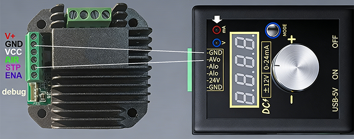
| STP | Step Voltage Signal Input | Analog Voltage Signal: 0-5V or 0-10V |
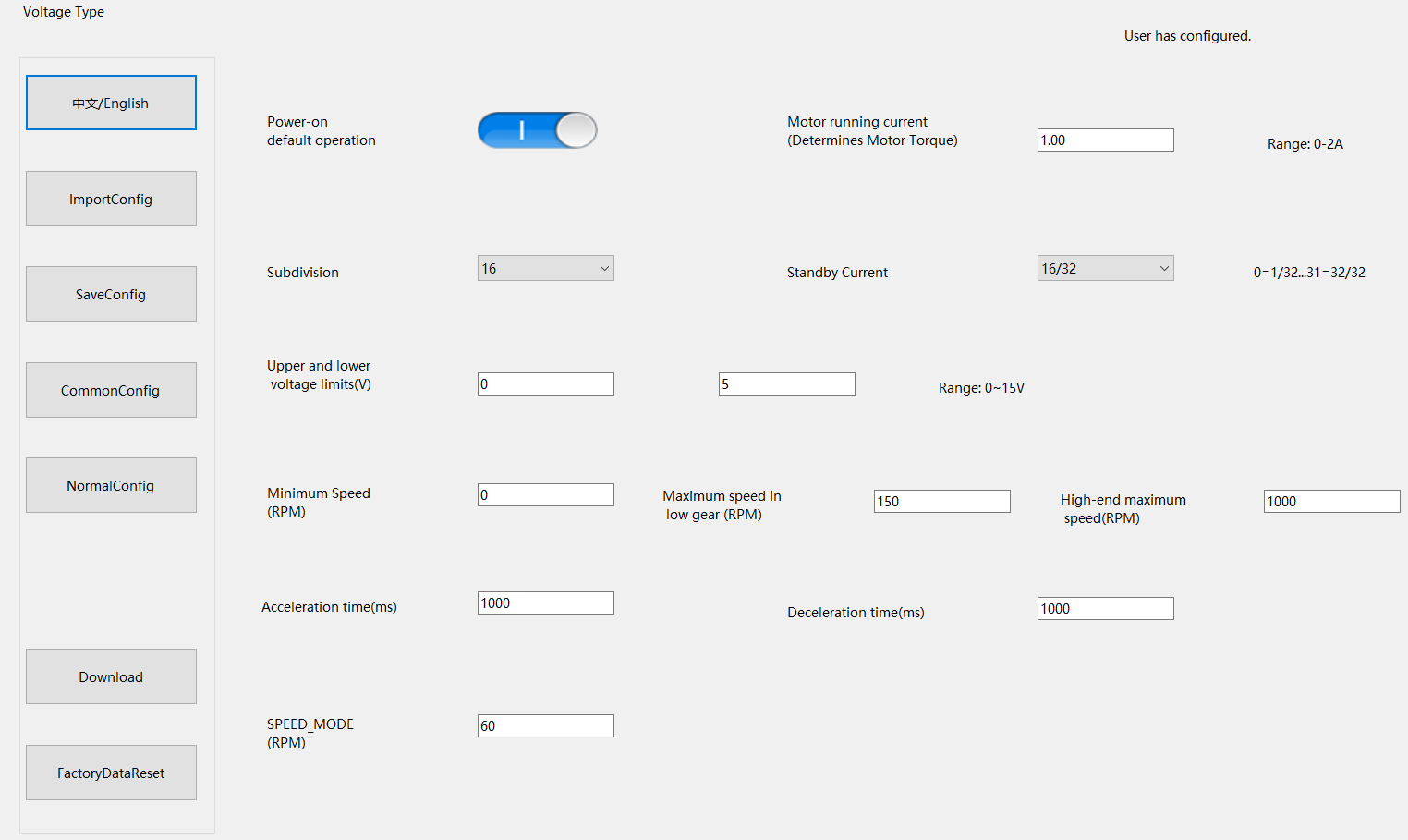
Voltage Range 0-15V (Max voltage customizable via software within 15V) |
| ENA | Enable Control Signal Input | Floating: Enable; GND: disable |
Vmax = 5.5V, Vmin = 2.1V Typical Value: 5V |
| Light Display | Function Description | Solution |
|---|---|---|
| Red, Green, Blue Alternating Flash | Chip configuration not written | Write configuration software program via the flashing port |
| Red Light Fast Flash | Low Voltage or High Voltage Alarm | Adjust power supply voltage to within the specified range |
| Green Light Fast Flash | High Temperature Alarm | Add heat dissipation measures |
| Blue Light Fast Flash | Motor Overcurrent Alarm | Check for motor short circuit or other overcurrent conditions after power off |
| White Light Slow Flash | Motor Normal Operation | - |
Connects to a two-phase four-wire motor via A+/A-, B+/B- interfaces. The internal drive circuit converts control signals into coil current to achieve stepping.
High/Low level. The motor working state can be configured in software, allowing for motor free state (energy saving / emergency stop).
Changes the level to switch the motor rotation direction.
Receives analog voltage signal. The specific voltage corresponding to rotation speed is set in the software.
Switch to the low speed range, default high speed range when floating, Must be set when the motor is stopped.
| Fault Phenomenon | Possible Cause | Solution |
|---|---|---|
| Motor does not rotate |
1. 24V power not connected or reversed. 2. ENA has no valid enable signal. 3. Motor wiring error/open circuit. 4. STP signal abnormal. |
1. Check power wiring. 2. Confirm ENA level. 3. Verify coil wiring. 4. Check controller output. |
| Motor jitters / loses steps |
1. Rotation speed too high. 2. Load too large. 3. Acceleration time too short when switching direction at high speed. |
1. Adjust input voltage. 2. Reduce load / replace with higher torque motor. 3. Stop voltage output before switching direction. |
| Motor direction abnormal |
1. DIR level reversed. 2. A/B phase coils reversed. |
1. Adjust DIR logic. 2. Swap A+/A- or B+/B-. |
| Driver overheats severely |
1. Drive current set too high. 2. Poor heat dissipation. 3. Motor short circuit. |
1. Reduce running current in software. 2. Strengthen heat dissipation. 3. Check motor coils. |