
Adampower
![]()

4~20 mA Current-Adjustable Stepper Motor Driver
Product Introduction
4~20 mA current-adjustable stepping motor driver is a compact and versatile solution designed for precise speed control via analog current signal. It features miniature size, wide voltage input, and seamless integration with NEMA17 and NEMA23 stepper motors.
The driver accepts 4~20 mA analog current input corresponding to 0~300 RPM speed output (default setting for peristaltic pumps), making it ideal for applications requiring adjustable speed control without complex digital communication.
Product Advantages
- Miniature Size: Ultra-compact 42.2mm × 42.2mm × 14.5mm design saves installation space.
- Wide Voltage Input: DC 12~40VDC input range, recommended working voltage 24VDC.
- High Output Current: Continuous output current 1.4A max, peak current 2.0A.
- Flexible Integration: Integrated design, mountable with NEMA17 and NEMA23 stepper motors.
- Smooth Operation: Low vibration, low noise, stable operation, low motor heating.
- Adjustable Speed: 4~20 mA current corresponding to 0~300 RPM speed range (customizable on request).
Electrical Characteristics
| Parameter | Minimum Value | Typical Value | Maximum Value | Unit |
|---|---|---|---|---|
| Supply Voltage (DC) | 12 | 24 | 40 | VDC |
| Control Signal Input Current | 4 | 10 | 20 | mA |

Product Images


Pin Definition
| Pin No. | Name | Description |
|---|---|---|
| 1 | 24V | Supply voltage: 12-40VDC, Recommend DC24V |
| 2 | GND | Supply Voltage Ground: GND/0V |
| 3 | H/L | Default High Speed Range; Connect GND to Low Speed Range |
| 4 | DIR | The rotation direction of the motor, CW/CCW |
| 5 | STP | The positive pole of the speed-regulating current |
| 6 | ENA | Enable the Stepper Motor |
| 7 | DEBUG | Debug port |
Wiring Diagram

Debug Cable & Software


Demo Video
Customized Working Speed Range 0-300RPM for peristaltic pumps requirement. Adjusting current: 4~20mA corresponding to Speed: 0~300RPM:
Integrated Stepper Motor Assembly
When this NEMA17 Sized Driver assembled with NEMA23 motor via a flange, an Integrated Stepper Motor is formed:

Downloads & Support
- User Manual: Current Stepper Motor Driver User Manual

- Debug Software: Debugging Software Download
More Information on detail, please feel free to contact me 

4~20 mA Current-Adjustable Stepper Motor Driver
Product Introduction
4~20 mA current-adjustable stepping motor driver is a compact and versatile solution designed for precise speed control via analog current signal. It features miniature size, wide voltage input, and seamless integration with NEMA17 and NEMA23 stepper motors.
The driver accepts 4~20 mA analog current input corresponding to 0~300 RPM speed output (default setting for peristaltic pumps), making it ideal for applications requiring adjustable speed control without complex digital communication.
Product Advantages
- Miniature Size: Ultra-compact 42.2mm × 42.2mm × 14.5mm design saves installation space.
- Wide Voltage Input: DC 12~40VDC input range, recommended working voltage 24VDC.
- High Output Current: Continuous output current 1.4A max, peak current 2.0A.
- Flexible Integration: Integrated design, mountable with NEMA17 and NEMA23 stepper motors.
- Smooth Operation: Low vibration, low noise, stable operation, low motor heating.
- Adjustable Speed: 4~20 mA current corresponding to 0~300 RPM speed range (customizable on request).
Electrical Characteristics
| Parameter | Minimum Value | Typical Value | Maximum Value | Unit |
|---|---|---|---|---|
| Supply Voltage (DC) | 12 | 24 | 40 | VDC |
| Control Signal Input Current | 4 | 10 | 20 | mA |
Product Images
Pin Definition
| Pin No. | Name | Description |
|---|---|---|
| 1 | 24V | Supply voltage: 12-40VDC, Recommend DC24V |
| 2 | GND | Supply Voltage Ground: GND/0V |
| 3 | H/L | Default High Speed Range; Connect GND to Low Speed Range |
| 4 | DIR | The rotation direction of the motor, CW/CCW |
| 5 | STP | The positive pole of the speed-regulating current |
| 6 | ENA | Enable the Stepper Motor |
| 7 | DEBUG | Debug port |
Wiring Diagram
Debug Cable & Software
Demo Video
Customized Working Speed Range 0-300RPM for peristaltic pumps requirement. Adjusting current: 4~20mA corresponding to Speed: 0~300RPM:
Integrated Stepper Motor Assembly
When this NEMA17 Sized Driver assembled with NEMA23 motor via a flange, an Integrated Stepper Motor is formed:
Downloads & Support
- User Manual: Current Stepper Motor Driver User Manual
- Debug Software: Debugging Software Download
More Information on detail, please feel free to contact me


| Motor Type | Bipolar stepper |
| Step Angle | 1.8° |
| Voltage (V) | 3 / 3.6 |
| Current (A) | 6 |
| Resistance (Ohms) | 0.5 / 0.6 |
| Inductance (mH) | 4 / 8 |
| Lead Wires | 4 |
| Holding Torque (N.m) | 4 / 8 |
| Motor Length (mm) | 76 / 114 |
| Ambient Temperature | -20℃ ~ 50℃ |
| Temperature Rise | 80K Max. |
| Dielectric Strength | 1mA Max. @ 500V, 1KHz, 1Sec. |
| Insulation Resistance | 100MΩ Min. @500Vdc |
NEMA34 Hollow Shaft Stepper Motor

Electrical Specifications:
Model No. | Voltage/ Phase (V) | Current/ Phase (A) | Resistance/ Phase (Ω) | Inductance/ Phase (mH) | Number of Lead Wires | Rotor Inertia (g.cm2) | Holding Torque (N.m) | Motor Length L (mm) |
34HS76 | 3 | 6 | 0.5 | 4 | 4 | 1300 | 4 | 76 |
34HS114 | 3.6 | 6 | 0.6 | 8 | 4 | 2500 | 8 | 114 |
Mechanical Dimensions and Wiring Diagram:
Torque Performance Curve:
| 34HS76 | 34HS114 |
 |  |
Test Condition: Chopper drive, no ramping, half micro-stepping, drive voltage 40V
Lead Wire Mode Options:

More Information on detail, please feel free to contact me

| Motor Type | Bipolar stepper |
| Step Angle | 1.8° |
| Voltage (V) | 2.6 / 3.6 |
| Current (A) | 3 / 4 |
| Resistance (Ohms) | 0.86 / 0.76 |
| Inductance (mH) | 2.6 / 3.2 |
| Lead Wires | 4 |
| Holding Torque (N.m) | 1 / 1.8 |
| Motor Length (mm) | 55 / 75 |
| Ambient Temperature | -20℃ ~ 50℃ |
| Temperature Rise | 80K Max. |
| Dielectric Strength | 1mA Max. @ 500V, 1KHz, 1Sec. |
| Insulation Resistance | 100MΩ Min. @500Vdc |
NEMA23 Hollow Shaft Stepper Motor

Electrical Specifications:
Model No. | Voltage/ Phase (V) | Current/ Phase (A) | Resistance/ Phase (Ω) | Inductance/ Phase (mH) | Number of Lead Wires | Rotor Inertia (g.cm2) | Holding Torque (N.m) | Motor Length L (mm) |
23HS55 | 2.6 | 3 | 0.86 | 2.6 | 4 | 300 | 1 | 55 |
23HS75 | 3 | 4 | 0.76 | 3.2 | 4 | 480 | 1.8 | 75 |
Mechanical Dimensions and Wiring Diagram:
Torque Performance Curve:
| 23HS55 | 23HS75 |
 |  |
Test Condition: Chopper drive, no ramping, half micro-stepping, drive voltage 40V
More Information on detail, please feel free to contact me

| Motor Type | Bipolar stepper |
| Step Angle | 1.8° |
| Voltage (V) | 1.4 / 2.9 |
| Current (A) | 1.5 |
| Resistance (Ohms) | 0.95 / 1.9 |
| Inductance (mH) | 1.4 / 3.2 |
| Lead Wires | 4 |
| Holding Torque (N.m) | 0.14 / 0.2 |
| Motor Length (mm) | 34 / 47 |
| Ambient Temperature | -20℃ ~ 50℃ |
| Temperature Rise | 80K Max. |
| Dielectric Strength | 1mA Max. @ 500V, 1KHz, 1Sec. |
| Insulation Resistance | 100MΩ Min. @500Vdc |
NEMA14 Hollow Shaft Stepper Motor

Electrical Specifications:
Model No. | Voltage/ Phase (V) | Current/ Phase (A) | Resistance/ Phase (Ω) | Inductance/ Phase (mH) | Number of Lead Wires | Rotor Inertia (g.cm2) | Holding Torque (N.m) | Motor Length L (mm) |
14HS34 | 1.4 | 1.5 | 0.95 | 1.4 | 4 | 20 | 0.14 | 34 |
14HS47 | 2.9 | 1.5 | 1.9 | 3.2 | 4 | 30 | 0.2 | 47 |
Mechanical Dimensions and Wiring Diagram:
Torque Performance Curve:
| 14HS34 | 14HS47 |
 |  |
Test Condition: Chopper drive, no ramping, half micro-stepping, drive voltage 24V
More Information on detail, please feel free to contact me

| Motor Type | Bipolar stepper |
| Step Angle | 1.8° |
| Voltage (V) | 2.1 / 3.7 |
| Current (A) | 1 |
| Resistance (Ohms) | 2.1 / 3.7 |
| Inductance (mH) | 1.5 / 2.3 |
| Lead Wires | 4 |
| Holding Torque (N.m) | 0.05 / 0.1 |
| Motor Length (mm) | 34 / 45 |
| Ambient Temperature | -20℃ ~ 50℃ |
| Temperature Rise | 80K Max. |
| Dielectric Strength | 1mA Max. @ 500V, 1KHz, 1Sec. |
| Insulation Resistance | 100MΩ Min. @500Vdc |
NEMA11 Hollow Shaft Stepper Motor

Electrical Specifications:
Model No. | Voltage/ Phase (V) | Current/ Phase (A) | Resistance/ Phase (Ω) | Inductance/ Phase (mH) | Number of Lead Wires | Rotor Inertia (g.cm2) | Holding Torque (N.m) | Motor Length L (mm) |
11HS34 | 2.1 | 1 | 2.1 | 1.5 | 4 | 9 | 0.05 | 34 |
11HS45 | 3.7 | 1 | 3.7 | 2.3 | 4 | 13 | 0.1 | 45 |
Mechanical Dimensions and Wiring Diagram:
Torque Performance Curve:
| 11HS34 | 11HS45 |
 |  |
Test condition: Chopper drive, no ramping, half micro-stepping, drive voltage 24V
More Information on detail, please feel free to contact me

| Step Accuracy: | ±5% | Resistance Accuracy: | ±10% |
|---|---|---|---|
| Inductance Accuracy: | ±20% | Temperature Rise: | 80°C MAX |
| Ambient Temperature Range: | -20°C~ 50°C | Storage Temperature Range: | -30°C~ 60°C |
| Insulation Resistance: | 100M Ω MIN. 500V DC | Dielectric Strength: | 500V AC 1min |
| Radial Play: | 0.02mm MAX. (450g Load) | End Play: | 0.08mm MAX. (450g Load) |
| Max. Radial Force: | 20N | Max. Axial Force: | 2N |
NEMA17 Hollow Shaft Stepper Motor

Electrical Specifications:
| Motor Type | Bipolar stepper |
| Step Angle | 1.8° |
| Voltage (V) | 2.6 / 3.3 / 2 / 2.5 |
| Current (A) | 1.5 / 1.5 / 2.5 / 2.5 |
| Resistance (Ohms) | 1.8 / 2.2 / 0.8 / 1 |
| Inductance (mH) | 2.6 / 4.6 / 1.8 / 2.8 |
| Lead Wires | 4 |
| Holding Torque (N.m) | 0.22 / 0.35 / 0.5 / 0.6 |
| Motor Length (mm) | 34 / 40 / 48 / 60 |
| Ambient Temperature | -20℃ ~ 50℃ |
| Temperature Rise | 80K Max. |
| Dielectric Strength | 1mA Max. @ 500V, 1KHz, 1Sec. |
| Insulation Resistance | 100MΩ Min. @500Vdc |
Radial clearance | 0.02mm Max (450g load) | Insulation resistance | 100MΩ @500VDC |
Axial clearance | 0.08mm Max (450g load) | Dielectric strength | 500VAC, 1mA, 1s@1KHZ |
Max radial load | 25N (20mm from flange surface) | Insulation class | Class B (80K) |
Max axial load | 10N | Ambient temperature | -20℃ ~ 50℃ |
Model No. | Voltage/ Phase (V) | Current/ Phase (A) | Resistance/ Phase (Ω) | Inductance/ Phase (mH) | Number of Lead Wires | Rotor Inertia (g.cm2) | Holding Torque (N.m) | Motor Length L (mm) |
17HS34 | 2.6 | 1.5 | 1.8 | 2.6 | 4 | 35 | 0.22 | 34 |
17HS40 | 3.3 | 1.5 | 2.2 | 4.6 | 4 | 55 | 0.35 | 40 |
17HS48 | 2 | 2.5 | 0.8 | 1.8 | 4 | 70 | 0.5 | 48 |
17HS60 | 2.5 | 2.5 | 1 | 2.8 | 4 | 105 | 0.6 | 60 |
Mechanical Dimensions and Wiring Diagram:
Torque Performance Curve:
| 17HS34 | 17HS40 |
 |  |
| 17HS48 | 17HS60 |
 |  |
Test Condition: Chopper drive, no ramping, half micro-stepping, drive voltage 40V
More Information on detail, please feel free to contact me


| Step Accuracy: | ±5% | Resistance Accuracy: | ±10% |
|---|---|---|---|
| Inductance Accuracy: | ±20% | Temperature Rise: | 80°C MAX |
| Ambient Temperature Range: | -20°C~ 50°C | Storage Temperature Range: | -30°C~ 60°C |
| Insulation Resistance: | 100M Ω MIN. 500V DC | Dielectric Strength: | 500V AC 1min |
| Radial Play: | 0.02mm MAX. (450g Load) | End Play: | 0.08mm MAX. (450g Load) |
| Max. Radial Force: | 20N | Max. Axial Force: | 2N |
NEMA6 Hollow Shaft Stepper Motor
Electrical Specifications:
Model No. | Step Angle | Motor Length (mm) | Rated voltage (v) | Rated Current (A) | Phase Resistance (Ω) | Phase Indutance (Mh) | Holding Torque(MIN) N.m | Detent Toruue(MAX) N.cm | Motor Torque (g.cm2) |
| 6HS30 | 1.8 | 32 | 6.6 | 0.3 | 22 | 3.6 | 0.005 | 0.002 | 2.5 |
Mechanical Dimensions and Wiring Diagram:
Torque Performance Curve: 
More Information on detail, please feel free to contact me

Model No. | Motor Size | Voltage/ Phase (V) | Current/ Phase (A) | Resistance/ Phase (Ω) | Inductance/ Phase (mH) | Number of Lead Wires | Rotor Inertia (g.cm2) | Holding Torque (N.m) | Motor Length L (mm) |
8HS30 | 20 | 2.5 | 0.5 | 5.1 | 1.5 | 4 | 2 | 0.02 | 30 |
8HS42 | 20 | 6.3 | 0.5 | 12.5 | 4.5 | 4 | 3 | 0.04 | 42 |
NEMA8 Hollow Shaft Stepper Motor
Electrical Specifications:
| Motor Type | Bipolar stepper |
| Step Angle | 1.8° |
| Voltage (V) | 2.5 / 6.3 |
| Current (A) | 0.5 |
| Resistance (Ohms) | 5.1 / 12.5 |
| Inductance (mH) | 1.5 / 4.5 |
| Lead Wires | 4 |
| Holding Torque (N.m) | 0.02 / 0.04 |
| Motor Length (mm) | 30 / 42 |
| Ambient Temperature | -20℃ ~ 50℃ |
| Temperature Rise | 80K Max. |
| Dielectric Strength | 1mA Max. @ 500V, 1KHz, 1Sec. |
| Insulation Resistance | 100MΩ Min. @500Vdc |
Mechanical Dimensions and Wiring Diagram:
Torque Performance Curve:
| 8HS30 | 8HS42 |
 |  |
More Information on detail, please feel free to contact me


The IM34ET Series Integrated Motors represent a perfect integration of stepper drivers and stepper motors, combining the technologies of both in a single unit. They are fully compatible with 1599-revolution mechanical absolute encoders, which not only save installation space but also streamline wiring connections. By reducing your design and production costs, they stand as the premier choice for your stepper system solutions.
Frame Size: NEMA34
Holding Torque: 4.5–12.5 N·m
Supply Voltage: 18–70 VAC
Supported Protocols: Modbus/RTU, RS485
Built-in Programmable Multi-Turn Feedback: 1599 revolutions; supports user-defined home position with memory, no sensor required
Software Limit Function Supported: More reliable than mechanical limit switches
Closed-Loop Control: 4096-line (16384 counts) encoder feedback
Torque Modes Supported: Homing on collision, constant torque, object gripping
Input Compatibility: 5–24 VDC; Output: Open-collector (OC) output, withstanding voltage up to 30 VDC
Comprehensive Protection Features: Over-voltage, under-voltage, over-current, winding open-circuit, and position deviation protection
Non-Volatile Memory: Configuration parameters stored in the on-chip FLASH of the MCU
Wide Filter Frequency Range: 50 kHz–5 MHz adjustable, factory default at 300 kHz
User-friendly PC interface with full-featured functionality
Motor Parameters
| Model No. | Length L (mm) | Total Length (mm) | Shaft Length (mm) | Shaft Dia. (mm) | Phase Current (A) | Resistance (Ω) | Inductance (mH) | Holding Torque (N.m) | Inertia (g.cm²) | Weight (g) |
|---|---|---|---|---|---|---|---|---|---|---|
| IM3445 | 78.1 | 102.6 | 32 | 14 | 6 | 0.37 | 2.8 | 4.5 | 1800 | 2200 |
| IM3465 | 98.6 | 122.1 | 32 | 14 | 6 | 0.45 | 4.0 | 6.5 | 2800 | 3000 |
| IM3485 | 117.6 | 142.1 | 32 | 14 | 6 | 0.59 | 5.5 | 8.5 | 3600 | 3700 |
| IM34125 | 156.1 | 180.6 | 32 | 14 | 6 | 0.679 | 8.2 | 12.5 | 5400 | 5500 |

RS485 Multi-turn Absolute Encoder type Integrated Stepper Motor
Terminal Definition
| Terminal | Color | Name | Description |
|---|---|---|---|
| 1 | Red | V | 24~100VDC(or 18-70VAC) |
| 2 | Black | V- | GND |
| 3 | Yellow | X com | COM /VCC COM, compatible with 5–24 VDC |
| 4 | Yel/BLK | X0 | 3 Programmable Inputs (Active Low) Port functions configurable via commands or host computer. Pulse Mode: X0 = Pulse, X1 = Direction |
| 5 | Blue | X1 | |
| 6 | Blu/BLK | X2 | |
| 7 | Green | Y2 | Y0: Default alarm output, Normally Closed (NC), Y1: Default position reached output, Normally Closed (NC) Y2: Undefined,Users may configure or redefine the functions of the corresponding ports via commands. Y2 can be customized to input X3 upon request before delivery; it defaults to an output port. |
| 8 | Gre/BLK | Y1 | |
| 9 | Purple | Y0 | |
| 10 | Pur/BLK | Y com | COM GND |
| 11 | Orange | 485A | RS485 Communication port, default baud rate is 115200 |
| 12 | Ora/BLK | 485B |

3-channel isolated digital signal input, the function of each input channel can be configured via software or commands, with the correspondence between input signals and functions as follows:
| Signal | Interface | Function |
|---|---|---|
| X0 | X0,Xcom | • General Input (Default) • Pulse / Limit / Home / Emergency Stop / Speed Switch / Interrupt Positioning / Forward Rotation |
| X1 | X1,Xcom | • General Input (Default) • Pulse / Direction / Limit / Home / Emergency Stop / Speed Switch / Interrupt Positioning / Reverse Rotation |
| X2 | X2,Xcom | • General Input (Default) • Limit / Home / Emergency Stop / Speed Switch / Interrupt Positioning |
XCOM is the common positive terminal for single-ended input signals and shall be connected to the positive pole of the power supply.
It only accepts sinking NPN signals.
The figure below illustrates the typical wiring configurations for the X0–X2 input ports.

3-channel isolated digital signal output, the function of each output channel can be configured via software or commands, with the correspondence between output signals and functions as follows:
| Signal | Interface | Function |
|---|---|---|
| Y0 | Y0, Ycom | • Alarm Output (Default) • Alarm / Position Reached / Running Status |
| Y1 | Y1, Ycom | • Position Reached Output (Closed Loop Default) • Running Status Output (Open Loop Default) • Alarm / Position Reached / Running Status |
| Y2 | Y2, Ycom | • General Purpose Output (Default) • Alarm / Position Reached / Running Status |
The figure below illustrates the typical wiring configurations for the Y0–Y2 output ports.

Warning: Output terminal → DC voltage < 30V, Inflow current ≤ 50mA.
CRC Check Routine (C#)
UInt16 Funct_CRC16(unsigned char * puchMsg, UInt16 DataLen)
{
UInt16 i,j,tmp;
UInt16 crcdata=0xFFFF;
for(i=0;i<DataLen;i )
{
crcdata=(*puchMsg)^crcdata;
puchMsg ;
for(j=0;j<8;j )
{
tmp=crcdata&0x0001;
crcdata=crcdata>>1;
if(tmp){
crcdata=crcdata^0xA001;
}
}
}
return crcdata;
}
RS485 Integrated Stepper Motor Commissioning and Control Software:
Modbus Poll 
New Software in google drive 
Github Project
Adampower

Quick Start Guide – Follow the steps below:
1. Extract the zip file, open CommFile folder and Click Step-Config.exe or Adampower.exe


2. Open Project.

3. Click Browse

4. Select the Project.prj in the Project folder, in the same path as CommFile.

5. Double Click the Project.prj path

6. Right Click Modbus_485, and Click Property:


7. Click Property ComNN, Choose COM port, Baud rate and click Save and OK.


8. Start to use software control the RS485 Integrated stepper motor by below buttons:


Optional: USB-TTL debugging cable
RS485 Stepper Motor Controller Commands Manual
LED indicator and status:

more Information on detail, please feel free to contact me

BT24 Industrial Bluetooth to RS485 Converter (BLE 5.1)
Industrial BLE 5.1 Bluetooth to RS485 Converter — Wireless Serial Port Adapter with Data Transparent Transmission.

Product Introduction
The BT24 is an industrial-grade Bluetooth 5.1 to RS485 converter designed for wireless communication between mobile devices and RS485 stepper motors or integrated stepper motors.
With data transparent transmission and Modbus protocol support, it enables convenient wireless control via Android APP, eliminating the need for physical serial cables.
Product Advantages
- Renesas DA14531 chip with PA Amplifiers
- Bluetooth BLE 5.1 technology
- Support interfaces: RS485
- Support ModBus protocol
- Support communication between Android and RS485 Stepper Motor or RS485 Integrated Stepper Motor
- Support changing baud rates: 2400, 4800, 9600, 19200, 38400, 57600, 115200
- External rubber stick antenna, visual distance: mobile phone: 90 m / PC: 70 m / device to device: 400 m
- Support power range: DC 5~36 V
- Device Size: 60 × 27.8 × 16.4 mm
- Working temperature: -40 to 85 °C

Electrical Characteristics
| Parameter | Value |
|---|---|
| Power Supply | DC 5~36 V |
| RS485 Default Baud Rate | 9600 bps |
| RS485 Load Capacity | Up to 32 devices |
| RS485 Communication Distance | 1200 m (at 9600 bps) |
| Working Mode | Point-to-point half-duplex, point-to-multipoint half-duplex |
| Direction Control | Automatic |
| Power Supply Requirement | 5 V / 1 A |
| Working Temperature | -40 to 85 °C |
| Dimensions | 60 × 27.8 × 16.4 mm |
BLE UUID
- SERVICE UUID: FFE0
- NOTIFY/WRITE UUID: FFE1
- WRITE UUID: FFE2

Baud Rate Switch
Short press the KEY twice consecutively to switch the baud rate once. The number of times the blue light blinks represents the baud rate number.
| Flash Count | Baud Rate |
|---|---|
| 1 | 2400 |
| 2 | 4800 |
| 3 | 9600 |
| 4 | 19200 |
| 5 | 38400 |
| 6 | 57600 |
| 7 | 115200 |
Application Scenarios
- Wireless motor control — Control RS485 stepper motors via Android APP over Bluetooth
- Industrial automation — Replace wired serial connections with reliable wireless communication
- Remote monitoring — Real-time data transmission over distances up to 400 m (device to device)
- Field maintenance — Quick and convenient parameter adjustment via mobile phone
Android APP Control
AR Series RS485 Integrated Stepper Motor
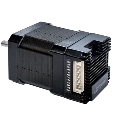
Bluetooth to RS485 Converter and Android APP designed for AR Series RS485 Integrated Stepper Motor.
 |  |  |

Download the Android APP
IG Series RS485 Integrated Stepper Motor
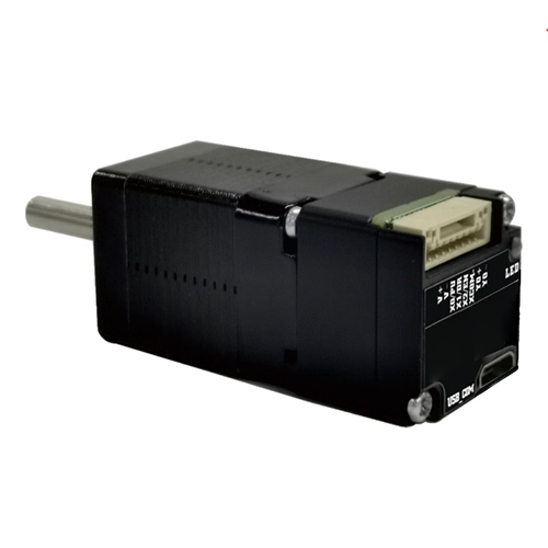
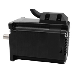
Bluetooth to RS485 Converter and Android APP designed for IG Series RS485 Integrated Stepper Motor.
 |  |  | 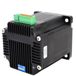 |

Download the Android APP
More Information on detail, please feel free to contact me

The IG34 series integrated motor is the perfect combination of drive and stepper motor,
which perfectly integrates stepper motor and drive technology, also built in 1000 line encoder,
it can save installation space, Simultaneously saving design and production costs,
supporting RS485 and TTL communication.
| Item | Specifications |
| Stepper Motor Size | NEMA34 |
| Encoder type | 1000 line encoder |
| Working voltage | 24~80VDC, 18~60VAC |
| Driver Current | 0.5-6.5A |
| Velocity range | Up to 3000RPM |
| Control Method | RS485, Pulse& Direction, Twin-Pulse, I/O, Built-in Program |
| Torque value | 3.5 -12.5Nm |
| Nonvolatile storage | Configuration parameters are stored in FLASH inside the MCU |
| DI and DO | 2 DI, 1 DO |
| Protection | Overvoltage, undervoltage, overcurrent, open winding, position deviation |
| Digital Input (2/3) | Receive 3.3-24VDC | ||
| Digital Output(1) | Maximum withstand voltage of 30V, | ||
| Maximum input or output current 30mA | |||
Motor Parameters
| Model No. | length mm L | Shaft length mm | Shaft dia. mm | Phase current A | Resistance Ω | inductance mH | Hold torque N.m | Inertia g.cm² | Weight g |
| IG3445 | 80 | 32 | 14 | 6 | 0.5 | 3.6 | 4.5 | 1950 | 2900 |
| IG23465 | 98 | 32 | 14 | 6 | 0.63 | 4.5 | 6.5 | 2500 | 3400 |
| IG3485 | 118 | 32 | 14 | 6 | 0.5 | 4.2 | 8.5 | 2800 | 4100 |
| IG34125 | 151 | 32 | 14 | 6 | 0.63 | 4.7 | 12.5 | 4950 | 5600 |

Wiring Diagram:
1. Pulse Type Integrated Stepper Motor, Terminal Definition

Terminal Definition
| Terminal | Name | Description | |
| 1 | V | 24~60VDC | |
| 2 | V- | GND | |
| 3 | X0 (PU ) | Optoelectronic isolation, differential, High level can directly receive 3.3-24VDC, with a minimum pulse width of 2us, The maximum pulse frequency is 400KHz, which can be used as a universal input port for Pulse/Direction | |
| 4 | X0-(PU-) | ||
| 5 | X1 (DR ) | ||
| 6 | X1-(DR-) | ||
| 7 | X2(EN ) | Optoelectronic isolation, differential, High level can directly receive 3.3-24VDC, with a minimum pulse width of 100us, The maximum pulse frequency is 10KHz, which can be used as a universal input port for Enable | |
| 8 | X2(EN-) | ||
| 9 | Y0 (AL ) | The default alarm output port can detect the driver alarm status and provide feedback to the main station. Other functions can be set through communication | |
| 10 | Y0-(AL-) | ||
| 11 | Y1(EX ) | The default In-place output , Other functions can be set through communication | |
| 12 | Y1(EX-) | ||
Set Micro-step by SW1, SW2, SW3 and SW4:
SW5=OFF: Pulse & Direction; SW=ON: Twin Pulse mode.
SW6=OFF: CW direction; SW6=ON: CCW direction.
2. RS485 Type Integrated Stepper Motor, Terminal Definition

Terminal Definition
| Terminal | Name | Description | |
| 1 | V | 24~60VDC | |
| 2 | V- | GND | |
| 3 | X0 (PU ) | Optoelectronic isolation, differential, High level can directly receive 3.3-24VDC, with a minimum pulse width of 2us, The maximum pulse frequency is 400KHz, which can be used as a universal input port for Pulse/Direction | |
| 4 | X0-(PU-) | ||
| 5 | X1 (DR ) | ||
| 6 | X1-(DR-) | ||
| 7 | X2 (EN ) | ||
| 8 | X2-(EN-) | ||
| 9 | Y0 (AL ) | The default alarm output port can detect the driver alarm status and provide feedback to the main station. Other functions can be set through communication | |
| 10 | Y0-(AL-) | ||
| 11 | 485A | RS485 Communication port, default baud rate is 115200 | |
| 12 | 485B | ||
Set Device ID for RS485 integrated Stepper Motor by SW1 ~ SW5:

SW6 is used to set the terminal resistance; OFF=0 ohms; ON=120 ohms
CRC Check Routine (C#)
UInt16 Funct_CRC16(unsigned char * puchMsg, UInt16 DataLen)
{
UInt16 i,j,tmp;
UInt16 crcdata=0xFFFF;
for(i=0;i<DataLen;i )
{
crcdata=(*puchMsg)^crcdata;
puchMsg ;
for(j=0;j<8;j )
{
tmp=crcdata&0x0001;
crcdata=crcdata>>1;
if(tmp){
crcdata=crcdata^0xA001;
}
}
}
return crcdata;
}
Software Tools for RS485 Control
Modbus Poll
New Software in google drive 
Github Project
Step-Config
1. Extract the zip file, open CommFile folder and Click Step-Config.exe or Adampower.exe
2. Open Project.
3. Click Browse
4. Select the Project.prj in the Project folder, in the same path as CommFile.
5. Double Click the Project.prj path
6. Right Click Modbus_485, and Click Property:
7. Click Property ComNN, Choose COM port, Baud rate and click Save and OK.
8. Start to use software control the RS485 Integrated stepper motor by below buttons:
RS485 Stepper Motor Controller Manual
Block Diagram:
2 Input signals can directly receive 3.3-24V DC levels at high levels, Max. frequency of 400KHZ.
X0: pulse input, IO start/stop, limit, direction, universal input.
X1 pulse input, IO start/stop, limit, direction, universal input.
...
1 Output signal, maximum withstand voltage 30V, maximum input or output current 30mA
Y0 : alarm output, universal output, and factory default alarm output.
LED indicator and status:

The IG11 series integrated motor is the perfect combination of drive and stepper motor,
which perfectly integrates stepper motor and drive technology, also built in 1000 line encoder,
it can save installation space, Simultaneously saving design and production costs,
supporting RS485 and TTL communication.
| Item | Specifications |
| Stepper Motor Size | NEMA11 |
| Encoder type | 1000 line encoder |
| Working voltage | 8~36VDC |
| Driver Current | 0.2-2.0A |
| Velocity range | Up to 3000RPM |
| Control Method | RS485, Pulse& Direction, Twin-Pulse, I/O, Built-in Program |
| Torque value | 0.08 - 0.24Nm |
| Nonvolatile storage | Configuration parameters are stored in FLASH inside the MCU |
| DI and DO | 2/3 DI, 1 DO |
| Protection | Overvoltage, undervoltage, overcurrent, open winding, position deviation |
| Digital Input (2/3) | Receive 3.3-24VDC | ||
| Digital Output(1) | Maximum withstand voltage of 30V, | ||
| Maximum input or output current 30mA | |||
Motor Parameters
NEMA11 integrated Stepper Motor:
| Model No. | length mm L | Shaft length mm | Shaft dia. mm | Phase current A | Resistance Ω | inductance mH | Hold torque N.m | Inertia g.cm² | Weight g |
| IG11008 | 31 | 26 | 5 | 1.0 | 1.5 | 1.1 | 0.08 | 9 | 115 |
| IG11018 | 52 | 26 | 5 | 1.3 | 2.4 | 2.3 | 0.18 | 18 | 205 |
| IG11024 | 63 | 26 | 5 | 1.5 | 1.8 | 2.1 | 0.24 | 30 | 268 |

Wiring Diagram:
1. Pulse Type Integrated Stepper Motor, Terminal Definition

Terminal Definition
| Terminal | Name | Description | |
| 1 | V | 8-36VDC | |
| 2 | V- | GND | |
| 3 | X0 (PU ) | Optoelectronic isolation, differential, High level can directly receive 3.3-24VDC, with a minimum pulse width of 2us, The maximum pulse frequency is 400KHz, which can be used as a universal input port for Pulse/Direction | |
| 4 | X0-(PU-) | ||
| 5 | X1 (DR ) | ||
| 6 | X1-(DR-) | ||
| 7 | X2(EN ) | Optoelectronic isolation, differential, High level can directly receive 3.3-24VDC, with a minimum pulse width of 100us, The maximum pulse frequency is 10KHz, which can be used as a universal input port for Enable | |
| 8 | X2(EN-) | ||
| 9 | Y0 (AL ) | The default alarm output port can detect the driver alarm status and provide feedback to the main station. Other functions can be set through communication | |
| 10 | Y0-(AL-) | ||
| 11 | Y1 | Default function is in-place output | |
| 12 | Y1- | ||
2. RS485 Type Integrated Stepper Motor, Terminal Definition

Terminal Definition
| Terminal | Name | Description | |
| 1 | V | 8-36VDC | |
| 2 | V- | GND | |
| 3 | X0 (PU ) | Optoelectronic isolation, differential, High level can directly receive 3.3-24VDC, with a minimum pulse width of 2us, The maximum pulse frequency is 400KHz, which can be used as a universal input port or a high-speed pulse input port | |
| 4 | X0-(PU-) | ||
| 5 | X1 (DR ) | ||
| 6 | X1-(DR-) | ||
| 7 | X2(EN ) | ||
| 8 | X2-(EN-) | ||
| 9 | Y0 (AL ) | The default alarm output port can detect the driver alarm status and provide feedback to the main station. Other functions can be set through communication | |
| 10 | Y0-(AL-) | ||
| 11 | 485A | RS485 Communication port, default baud rate is 115200, | |
| 12 | 485B | ||
CRC Check Routine (C#)
UInt16 Funct_CRC16(unsigned char * puchMsg, UInt16 DataLen)
{
UInt16 i,j,tmp;
UInt16 crcdata=0xFFFF;
for(i=0;i<DataLen;i )
{
crcdata=(*puchMsg)^crcdata;
puchMsg ;
for(j=0;j<8;j )
{
tmp=crcdata&0x0001;
crcdata=crcdata>>1;
if(tmp){
crcdata=crcdata^0xA001;
}
}
}
return crcdata;
}
Software Tools for RS485 Control
Modbus Poll
Software in google drive
Github Project
Step-Config
1. Extract the zip file, open CommFile folder and Click Step-Config.exe or Adampower.exe
2. Open Project.
3. Click Browse
4. Select the Project.prj in the Project folder, in the same path as CommFile.
5. Double Click the Project.prj path
6. Right Click Modbus_485, and Click Property:
7. Click Property ComNN, Choose COM port, Baud rate and click Save and OK.
8. Start to use software control the RS485 Integrated stepper motor by below buttons:
RS485 Stepper Motor Controller Manual
Block Diagram:
2 Input signals can directly receive 3.3-24V DC levels at high levels, Max. frequency of 400KHZ.
X0: pulse input, IO start/stop, limit, direction, universal input.
X1 pulse input, IO start/stop, limit, direction, universal input.
...
1 Output signal, maximum withstand voltage 30V, maximum input or output current 30mA
Y0 : alarm output, universal output, and factory default alarm output.
LED indicator and status:

The IG14 series integrated motor is the perfect combination of drive and stepper motor,
which perfectly integrates stepper motor and drive technology, also built in 1000 line encoder,
it can save installation space, Simultaneously saving design and production costs,
supporting RS485 and TTL communication.
| Item | Specifications |
| Stepper Motor Size | NEMA14 |
| Encoder type | 1000 line encoder |
| Working voltage | 8 ~ 36VDC |
| Driver Current | 0.2-2.0A |
| Velocity range | Up to 3000RPM |
| Control Method | RS485, Pulse& Direction, Twin-Pulse, I/O, Built-in Program |
| Torque value | 0.2 - 0.4Nm |
| Nonvolatile storage | Configuration parameters are stored in FLASH inside the MCU |
| DI and DO | 2/3 DI, 1 DO |
| Protection | Overvoltage, undervoltage, overcurrent, open winding, position deviation |
| Digital Input (2/3) | Receive 3.3-24VDC | ||
| Digital Output(1) | Maximum withstand voltage of 30V, | ||
| Maximum input or output current 30mA | |||
Motor Parameters
Pulse type NEMA14 integrated Stepper Motor:
| Model No. | length mm L | Shaft length mm | Shaft dia. mm | Phase current A | Resistance Ω | inductance mH | Hold torque N.m | Inertia g.cm² | Weight g |
| IG1418 | 32 | 24 | 5 | 1.5 | 1.5 | 1.6 | 0.18 | 15 | 200 |
| IG1425 | 37 | 24 | 5 | 1.5 | 1.5 | 2.0 | 0.25 | 26 | 250 |
| IG1440 | 50 | 24 | 5 | 1.8 | 1.1 | 2.5 | 0.40 | 38 | 350 |
RS485 type NEMA14 integrated Stepper Motor:
| Model No. | length mm L | Shaft length mm | Shaft dia. mm | Phase current A | Resistance Ω | inductance mH | Hold torque N.m | Inertia g.cm² | Weight g |
| IG1412 | 26 | 24 | 5 | 1.0 | 1.5 | 1.9 | 0.12 | 8 | 230 |
| IG1420 | 34 | 24 | 5 | 1.5 | 2.1 | 2.1 | 0.20 | 14 | 290 |
| IG1425 | 40 | 24 | 5 | 1.5 | 2.5 | 2.8 | 0.25 | 20 | 340 |
| IG1435 | 53 | 24 | 5 | 1.8 | 2.9 | 4.8 | 0.35 | 31 | 440 |

Wiring Diagram:
1. Pulse Type Integrated Stepper Motor, Terminal Definition

Terminal Definition
| Terminal | Name | Description | |
| 1 | V | 8-48VDC | |
| 2 | V- | GND | |
| 3 | X0 (PU ) | Optoelectronic isolation, differential, High level can directly receive 3.3-24VDC, with a minimum pulse width of 2us, The maximum pulse frequency is 400KHz, which can be used as a universal input port for Pulse/Direction | |
| 4 | X0-(PU-) | ||
| 5 | X1 (DR ) | ||
| 6 | X1-(DR-) | ||
| 7 | X2(EN ) | Optoelectronic isolation, differential, High level can directly receive 3.3-24VDC, with a minimum pulse width of 100us, The maximum pulse frequency is 10KHz, which can be used as a universal input port for Enable | |
| 8 | X2(EN-) | ||
| 9 | Y0 (AL ) | The default alarm output port can detect the driver alarm status and provide feedback to the main station. Other functions can be set through communication | |
| 10 | Y0-(AL-) | ||
| 11 | Y1 | Default function is in-place output | |
| 12 | Y1- | ||
2. RS485 Type Integrated Stepper Motor, Terminal Definition

Terminal Definition
| Terminal | Name | Description | |
| 1 | V | 8-48VDC | |
| 2 | V- | GND | |
| 3 | X0 (PU ) | Optoelectronic isolation, differential, High level can directly receive 3.3-24VDC, with a minimum pulse width of 2us, The maximum pulse frequency is 400KHz, which can be used as a universal input port or a high-speed pulse input port | |
| 4 | X0-(PU-) | ||
| 5 | X1 (DR ) | ||
| 6 | X1-(DR-) | ||
| 7 | X2 | ||
| 8 | X2- | ||
| 9 | Y0 (AL ) | The default alarm output port can detect the driver alarm status and provide feedback to the main station. Other functions can be set through communication | |
| 10 | Y0-(AL-) | ||
| 11 | 485A | RS485 Communication port, default baud rate is 115200, | |
| 12 | 485B | ||
CRC Check Routine (C#)
UInt16 Funct_CRC16(unsigned char * puchMsg, UInt16 DataLen)
{
UInt16 i,j,tmp;
UInt16 crcdata=0xFFFF;
for(i=0;i<DataLen;i )
{
crcdata=(*puchMsg)^crcdata;
puchMsg ;
for(j=0;j<8;j )
{
tmp=crcdata&0x0001;
crcdata=crcdata>>1;
if(tmp){
crcdata=crcdata^0xA001;
}
}
}
return crcdata;
}
Software Tools for RS485 Control
Modbus Poll
Software in google drive
Github Project
Step-Config
1. Extract the zip file, open CommFile folder and Click Step-Config.exe or Adampower.exe
2. Open Project.
3. Click Browse
4. Select the Project.prj in the Project folder, in the same path as CommFile.
5. Double Click the Project.prj path
6. Right Click Modbus_485, and Click Property:
7. Click Property ComNN, Choose COM port, Baud rate and click Save and OK.
8. Start to use software control the RS485 Integrated stepper motor by below buttons:
RS485 Stepper Motor Controller Manual
Block Diagram:
2 Input signals can directly receive 3.3-24V DC levels at high levels, Max. frequency of 400KHZ.
X0: pulse input, IO start/stop, limit, direction, universal input.
X1 pulse input, IO start/stop, limit, direction, universal input.
...
1 Output signal, maximum withstand voltage 30V, maximum input or output current 30mA
Y0 : alarm output, universal output, and factory default alarm output.
LED indicator and status:

The IG24 series integrated motor is the perfect combination of drive and stepper motor,
which perfectly integrates stepper motor and drive technology, also built in 1000 line encoder,
it can save installation space, Simultaneously saving design and production costs,
supporting RS485 and TTL communication.
| Item | Specifications |
| Stepper Motor Size | NEMA24 |
| Encoder type | 1000 line encoder |
| Working voltage | 24-60VDC |
| Driver Current | 0.5-5A |
| Velocity range | Up to 3000RPM |
| Control Method | RS485, Pulse& Direction, Twin-Pulse, I/O, Built-in Program |
| Torque value | 1.6 - 3.5Nm |
| Nonvolatile storage | Configuration parameters are stored in FLASH inside the MCU |
| DI and DO | 2 DI, 1 DO |
| Protection | Overvoltage, undervoltage, overcurrent, open winding, position deviation |
| Digital Input (2/3) | Receive 3.3-24VDC | ||
| Digital Output(1) | Maximum withstand voltage of 30V, | ||
| Maximum input or output current 30mA | |||
Motor Parameters
| Model No. | length mm L | Shaft length mm | Shaft dia. mm | Phase current A | Resistance Ω | inductance mH | Hold torque N.m | Inertia g.cm² | Weight g |
| IG2422 | 68 | 21 | 8 | 5 | 0.33 | 1.05 | 2.2 | 490 | 1300 |
| IG2430 | 85 | 21 | 8 | 5 | 0.43 | 2.0 | 3.0 | 690 | 1500 |

Wiring Diagram:
1. Pulse Type Integrated Stepper Motor, Terminal Definition
Terminal Definition
| Terminal | Name | Description | |
| 1 | V | 24~60VDC | |
| 2 | V- | GND | |
| 3 | X0 (PU ) | Optoelectronic isolation, differential, High level can directly receive 3.3-24VDC, with a minimum pulse width of 2us, The maximum pulse frequency is 400KHz, which can be used as a universal input port for Pulse/Direction | |
| 4 | X0-(PU-) | ||
| 5 | X1 (DR ) | ||
| 6 | X1-(DR-) | ||
| 7 | X2(EN ) | Optoelectronic isolation, differential, High level can directly receive 3.3-24VDC, with a minimum pulse width of 100us, The maximum pulse frequency is 10KHz, which can be used as a universal input port for Enable | |
| 8 | X2(EN-) | ||
| 9 | Y0 (AL ) | The default alarm output port can detect the driver alarm status and provide feedback to the main station. Other functions can be set through communication | |
| 10 | Y0-(AL-) | ||
| 11 | Y1(EX ) | The default In-place output , Other functions can be set through communication | |
| 12 | Y1(EX-) | ||
Set Micro-step by SW1, SW2, SW3 and SW4:
SW5=OFF: Pulse & Direction; SW=ON: Twin Pulse mode.
SW6=OFF: CW direction; SW6=ON: CCW direction.
2. RS485 Type Integrated Stepper Motor, Terminal Definition
Terminal Definition
| Terminal | Name | Description | |
| 1 | V | 24~60VDC | |
| 2 | V- | GND | |
| 3 | X0 (PU ) | Optoelectronic isolation, differential, High level can directly receive 3.3-24VDC, with a minimum pulse width of 2us, The maximum pulse frequency is 400KHz, which can be used as a universal input port for Pulse/Direction/Enable | |
| 4 | X0-(PU-) | ||
| 5 | X1 (DR ) | ||
| 6 | X1-(DR-) | ||
| 7 | X2 (EN ) | ||
| 8 | X2-(EN-) | ||
| 9 | Y0 (AL ) | The default alarm output port can detect the driver alarm status and provide feedback to the main station. Other functions can be set through communication | |
| 10 | Y0-(AL-) | ||
| 11 | 485A | RS485 Communication port, default baud rate is 115200 | |
| 12 | 485B | ||
Set Device ID for RS485 integrated Stepper Motor by SW1 ~ SW5:
SW6 is used to set the terminal resistance; OFF=0 ohms; ON=120 ohms
CRC Check Routine (C#)
UInt16 Funct_CRC16(unsigned char * puchMsg, UInt16 DataLen)
{
UInt16 i,j,tmp;
UInt16 crcdata=0xFFFF;
for(i=0;i<DataLen;i )
{
crcdata=(*puchMsg)^crcdata;
puchMsg ;
for(j=0;j<8;j )
{
tmp=crcdata&0x0001;
crcdata=crcdata>>1;
if(tmp){
crcdata=crcdata^0xA001;
}
}
}
return crcdata;
}
Software Tools for RS485 Control
Modbus Poll
Software in google drive
Step-Config
1. Extract the zip file, open CommFile folder and Click Step-Config.exe or Adampower.exe
2. Open Project.
3. Click Browse
4. Select the Project.prj in the Project folder, in the same path as CommFile.
5. Double Click the Project.prj path
6. Right Click Modbus_485, and Click Property:
7. Click Property ComNN, Choose COM port, Baud rate and click Save and OK.
8. Start to use software control the RS485 Integrated stepper motor by below buttons:
RS485 Stepper Motor Controller Manual
Block Diagram:
2 Input signals can directly receive 3.3-24V DC levels at high levels, Max. frequency of 400KHZ.
X0: pulse input, IO start/stop, limit, direction, universal input.
X1 pulse input, IO start/stop, limit, direction, universal input.
...
1 Output signal, maximum withstand voltage 30V, maximum input or output current 30mA
Y0 : alarm output, universal output, and factory default alarm output.
LED indicator and status:

The IG23 series integrated motor is the perfect combination of drive and stepper motor,
which perfectly integrates stepper motor and drive technology, also built in 1000 line encoder,
it can save installation space, Simultaneously saving design and production costs,
supporting RS485 and TTL communication.
| Item | Specifications |
| Stepper Motor Size | NEMA23 |
| Encoder type | 1000 line encoder |
| Working voltage | 8-60VDC, Recommend DC36V |
| Driver Current | 0.5-5A |
| Velocity range | Up to 3000RPM |
| Control Method | RS485, Pulse& Direction, Twin-Pulse, I/O, Built-in Program |
| Torque value | 0.8 - 2.2Nm |
| Nonvolatile storage | Configuration parameters are stored in FLASH inside the MCU |
| DI and DO | 2 DI, 1 DO |
| Protection | Overvoltage, undervoltage, overcurrent, open winding, position deviation |
| Digital Input (2/3) | Receive 3.3-24VDC | ||
| Digital Output(1) | Maximum withstand voltage of 30V, | ||
| Maximum input or output current 30mA | |||
Motor Parameters
| Model No. | Total length | Motor Length L | Shaft length mm | Shaft dia. mm | Phase current A | Resistance Ω | inductance mH | Hold torque N.m | Inertia g.cm² | Weight g |
| IG2312 | 74 | 56 | 21 | 8 | 4 | 0.5 | 1.8 | 1.2 | 280 | 800 |
| IG2320 | 94 | 76 | 21 | 8 | 5 | 0.4 | 2.0 | 2.0 | 480 | 1100 |

Wiring Diagram:
1. Pulse Type Integrated Stepper Motor, Terminal Definition
Terminal Definition
| Terminal | Name | Description | |
| 1 | V | 24~60VDC | |
| 2 | V- | GND | |
| 3 | X0 (PU ) | Optoelectronic isolation, differential, High level can directly receive 3.3-24VDC, with a minimum pulse width of 2us, The maximum pulse frequency is 400KHz, which can be used as a universal input port for Pulse/Direction | |
| 4 | X0-(PU-) | ||
| 5 | X1 (DR ) | ||
| 6 | X1-(DR-) | ||
| 7 | X2(EN ) | Optoelectronic isolation, differential, High level can directly receive 3.3-24VDC, with a minimum pulse width of 100us, The maximum pulse frequency is 10KHz, which can be used as a universal input port for Enable | |
| 8 | X2(EN-) | ||
| 9 | Y0 (AL ) | The default alarm output port can detect the driver alarm status and provide feedback to the main station. Other functions can be set through communication | |
| 10 | Y0-(AL-) | ||
| 11 | Y1(EX ) | The default In-place output , Other functions can be set through communication | |
| 12 | Y1(EX-) | ||
Set Micro-step by SW1, SW2, SW3 and SW4:
SW5=OFF: Pulse & Direction; SW=ON: Twin Pulse mode.
SW6=OFF: CW direction; SW6=ON: CCW direction.
2. RS485 Type Integrated Stepper Motor, Terminal Definition
Terminal Definition
| Terminal | Name | Description | |
| 1 | V | 24~60VDC | |
| 2 | V- | GND | |
| 3 | X0 (PU ) | Optoelectronic isolation, differential, High level can directly receive 3.3-24VDC, with a minimum pulse width of 2us, The maximum pulse frequency is 400KHz, which can be used as a universal input port for Pulse/Direction/Enable | |
| 4 | X0-(PU-) | ||
| 5 | X1 (DR ) | ||
| 6 | X1-(DR-) | ||
| 7 | X2 (EN ) | ||
| 8 | X2-(EN-) | ||
| 9 | Y0 (AL ) | The default alarm output port can detect the driver alarm status and provide feedback to the main station. Other functions can be set through communication | |
| 10 | Y0-(AL-) | ||
| 11 | 485A | RS485 Communication port, default baud rate is 115200 | |
| 12 | 485B | ||
Set Device ID for RS485 integrated Stepper Motor by SW1 ~ SW5:
SW6 is used to set the terminal resistance; OFF=0 ohms; ON=120 ohms
CRC Check Routine (C#)
UInt16 Funct_CRC16(unsigned char * puchMsg, UInt16 DataLen)
{
UInt16 i,j,tmp;
UInt16 crcdata=0xFFFF;
for(i=0;i<DataLen;i )
{
crcdata=(*puchMsg)^crcdata;
puchMsg ;
for(j=0;j<8;j )
{
tmp=crcdata&0x0001;
crcdata=crcdata>>1;
if(tmp){
crcdata=crcdata^0xA001;
}
}
}
return crcdata;
}
Software Tools for RS485 Control
Modbus Poll
Software in google drive
Adampower
1. Extract the zip file, open CommFile folder and Click Step-Config.exe or Adampower.exe
2. Open Project.
3. Click Browse
4. Select the Project.prj in the Project folder, in the same path as CommFile.
5. Double Click the Project.prj path
6. Right Click Modbus_485, and Click Property:
7. Click Property ComNN, Choose COM port, Baud rate and click Save and OK.
8. Start to use software control the RS485 Integrated stepper motor by below buttons:
RS485 Stepper Motor Controller Manual
Block Diagram:
2 Input signals can directly receive 3.3-24V DC levels at high levels, Max. frequency of 400KHZ.
X0: pulse input, IO start/stop, limit, direction, universal input.
X1 pulse input, IO start/stop, limit, direction, universal input.
...
1 Output signal, maximum withstand voltage 30V, maximum input or output current 30mA
Y0 : alarm output, universal output, and factory default alarm output.
LED indicator and status:

The IG17 series integrated motor is the perfect combination of drive and stepper motor,
which perfectly integrates stepper motor and drive technology, also built in 1000 line encoder,
it can save installation space, Simultaneously saving design and production costs,
supporting RS485 and TTL communication.
| Item | Specifications |
| Stepper Motor Size | NEMA17 |
| Encoder type | 1000 line encoder |
| Working voltage | 8-50VDC, Recommend DC36V |
| Driver Current | 0.2-3.2A |
| Velocity range | Up to 3000RPM |
| Control Method | RS485, Pulse& Direction, Twin-Pulse, I/O, Built-in Program |
| Torque value | 0.2 - 6Nm |
| Nonvolatile storage | Configuration parameters are stored in FLASH inside the MCU |
| DI and DO | 2 DI, 1 DO |
| Protection | Overvoltage, undervoltage, overcurrent, open winding, position deviation |
| Digital Input (2/3) | Receive 3.3-24VDC | ||
| Digital Output(1) | Maximum withstand voltage of 30V, | ||
| Maximum input or output current 30mA | |||
Motor Parameters
| Model No. | length mm L | Shaft length mm | Shaft dia. mm | Phase current A | Resistance Ω | inductance mH | Hold torque N.m | Inertia g.cm² | Weight g |
| IG1704 | 40 | 21 | 8 | 2.0 | 2 | 4.2 | 0.4 | 57 | 380 |
| IG1705 | 48 | 21 | 8 | 2.0 | 1.3 | 2.9 | 0.5 | 82 | 460 |
| IG1706 | 60 | 21 | 8 | 2.5 | 1.3 | 3.2 | 0.6 | 116 | 700 |

Wiring Diagram:
1. Pulse Type Integrated Stepper Motor, Terminal Definition

Terminal Definition
| Terminal | Name | Description | |
| 1 | V | 8-48VDC | |
| 2 | V- | GND | |
| 3 | X0 (PU ) | Optoelectronic isolation, differential, High level can directly receive 3.3-24VDC, with a minimum pulse width of 2us, The maximum pulse frequency is 400KHz, which can be used as a universal input port for Pulse/Direction | |
| 4 | X0-(PU-) | ||
| 5 | X1 (DR ) | ||
| 6 | X1-(DR-) | ||
| 7 | X2(EN ) | Optoelectronic isolation, differential, High level can directly receive 3.3-24VDC, with a minimum pulse width of 100us, The maximum pulse frequency is 10KHz, which can be used as a universal input port for Enable | |
| 8 | X2(EN-) | ||
| 9 | Y0 (AL ) | The default alarm output port can detect the driver alarm status and provide feedback to the main station. Other functions can be set through communication | |
| 10 | Y0-(AL-) | ||
Set Micro-step by SW1, SW2, SW3 and SW4:
SW5=OFF: Pulse & Direction; SW=ON: Twin Pulse mode.
SW6=OFF: CW direction; SW6=ON: CCW direction.
2. RS485 Type Integrated Stepper Motor, Terminal Definition

Terminal Definition
| Terminal | Name | Description | |
| 1 | V | 8-48VDC | |
| 2 | V- | GND | |
| 3 | X0 (PU ) | Optoelectronic isolation, differential, High level can directly receive 3.3-24VDC, with a minimum pulse width of 2us, The maximum pulse frequency is 400KHz, which can be used as a universal input port or a high-speed pulse input port | |
| 4 | X0-(PU-) | ||
| 5 | X1 (DR ) | ||
| 6 | X1-(DR-) | ||
| 7 | 485A(EN ) | RS485 Communication port, default baud rate is 115200, | |
| 8 | 485B(EN-) | ||
| 9 | Y0 (AL ) | The default alarm output port can detect the driver alarm status and provide feedback to the main station. Other functions can be set through communication | |
| 10 | Y0-(AL-) | ||
Set Device ID for RS485 integrated Stepper Motor by SW1 ~ SW5:
SW6 is used to set the terminal resistance; OFF=0 ohms; ON=120 ohms
CRC Check Routine (C#)
UInt16 Funct_CRC16(unsigned char * puchMsg, UInt16 DataLen)
{
UInt16 i,j,tmp;
UInt16 crcdata=0xFFFF;
for(i=0;i<DataLen;i )
{
crcdata=(*puchMsg)^crcdata;
puchMsg ;
for(j=0;j<8;j )
{
tmp=crcdata&0x0001;
crcdata=crcdata>>1;
if(tmp){
crcdata=crcdata^0xA001;
}
}
}
return crcdata;
}
Software Tools for RS485 Control
Modbus Poll
Software in google drive
Step-Config
1. Extract the zip file, open CommFile folder and Click Step-Config.exe or Adampower.exe
2. Open Project.
3. Click Browse
4. Select the Project.prj in the Project folder, in the same path as CommFile.
5. Double Click the Project.prj path
6. Right Click Modbus_485, and Click Property:
7. Click Property ComNN, Choose COM port, Baud rate and click Save and OK.
8. Start to use software control the RS485 Integrated stepper motor by below buttons:
RS485 Stepper Motor Controller Manual
Block Diagram:
2 Input signals can directly receive 3.3-24V DC levels at high levels, Max. frequency of 400KHZ.
X0: pulse input, IO start/stop, limit, direction, universal input.
X1 pulse input, IO start/stop, limit, direction, universal input.
...
1 Output signal, maximum withstand voltage 30V, maximum input or output current 30mA
Y0 : alarm output, universal output, and factory default alarm output.
LED indicator and status:

The IG8 series integrated motor is the perfect combination of drive and stepper motor,
which perfectly integrates stepper motor and drive technology, also built in 1000 line encoder,
it can save installation space, Simultaneously saving design and production costs,
supporting RS485 communication.
| Item | Specifications |
| Stepper Motor Size | NEMA8 |
| Encoder type | 1000 line encoder |
| Working voltage | 6~24VDC |
| Driver Current | 0.2-1.5A |
| Velocity range | Up to 3000RPM |
| Control Method | RS485, Pulse& Direction, Twin-Pulse, I/O, Built-in Program |
| Torque value | 0.08 - 0.24Nm |
| Nonvolatile storage | Configuration parameters are stored in FLASH inside the MCU |
| Protection | Overvoltage, undervoltage, overcurrent, open winding, position deviation |
Motor Parameters
NEMA8 integrated Stepper Motor:
| Model No. | Hole Spacing | Flange dia. | length mm L | Shaft length mm | Shaft dia. mm | Phase current A | Resistance Ω | inductance mH | Hold torque N.m | Inertia g.cm² | Weight g |
| IG8002 | 15.4 | 16 | 28 | 18 | 4 | 0.6 | 6 | 3 | 0.015 | 2.5 | 70 |
| IG8004 | 15.4 | 16 | 38 | 18 | 4 | 1.0 | 3.2 | 1.3 | 0.04 | 3.3 | 90 |
| IG8002B | 16 | 15 | 28 | 18 | 4 | 0.6 | 6 | 3 | 0.015 | 2.5 | 70 |
| IG8004B | 16 | 15 | 38 | 18 | 4 | 1.0 | 3.2 | 1.3 | 0.04 | 3.3 | 90 |


1. Pulse Type NEMA8 Integrated Stepper Motor, Terminal definition.
Terminal Definition
| Terminal | Name | Description | |
| 1 | V | 6 ~ 24VDC | |
| 2 | V- | GND | |
| 3 | PU | Optoelectronic isolation, differential, High level can directly receive 3.3-24VDC, with a minimum pulse width of 2us, The maximum pulse frequency is 400KHz, which can be used as a universal input port Pulse/Direction | |
| 4 | DR | ||
| 5 | EN | Optoelectronic isolation, differential, High level can directly receive 3.3-24VDC, with a minimum pulse width of 100us, The maximum pulse frequency is 10KHz, which can be used as a universal input port for Enable | |
| 6 | COM- | Input common ground | |
| 7 | AL | The default alarm output port can detect the driver alarm status and provide feedback to the main station. Other functions can be set through communication | |
| 8 | AL- | ||
2. RS-485 Type NEMA8 Integrated Stepper Motor, Terminal definition

CRC Check Routine (C#)
UInt16 Funct_CRC16(unsigned char * puchMsg, UInt16 DataLen)
{
UInt16 i,j,tmp;
UInt16 crcdata=0xFFFF;
for(i=0;i<DataLen;i )
{
crcdata=(*puchMsg)^crcdata;
puchMsg ;
for(j=0;j<8;j )
{
tmp=crcdata&0x0001;
crcdata=crcdata>>1;
if(tmp){
crcdata=crcdata^0xA001;
}
}
}
return crcdata;
}
Software Tools for RS485 Control
Modbus Poll
New Software in google drive
Adampower.exe
1. Extract the zip file, open CommFile folder and Click Step-Config.exe or Adampower.exe
2. Open Project.
3. Click Browse
4. Select the Project.prj in the Project folder, in the same path as CommFile.
5. Double Click the Project.prj path
6. Right Click Modbus_485, and Click Property:
7. Click Property ComNN, Choose COM port, Baud rate and click Save and OK.
8. Start to use software control the RS485 Integrated stepper motor by below buttons:
RS485 Stepper Motor Controller Manual
Block Diagram:

2 Input signals can directly receive 3.3-24V DC levels at high levels, Max. frequency of 400KHZ.
X0: pulse input, IO start/stop, limit, direction, universal input.
X1 pulse input, IO start/stop, limit, direction, universal input.
...
1 Output signal, maximum withstand voltage 30V, maximum input or output current 30mA
Y0 : alarm output, universal output, and factory default alarm output.
LED indicator and status:
IM23ET Series NEMA23 Multi-Turn Absolute Encoder Integrated Stepper Motor (RS485 Modbus RTU)

Product Introduction
The IM23ET Series Integrated Motors represent a perfect integration of stepper drivers and stepper motors, combining the technologies of both in a single unit.
They are fully compatible with 1599-revolution mechanical absolute encoders, which not only save installation space but also streamline wiring connections.
By reducing your design and production costs, they stand as the premier choice for your stepper system solutions.

Product Advantages
- NEMA23 frame size with holding torque from 0.8 to 3.0 N·m
- Supply voltage: 24–60 VDC
- Supported protocols: Modbus/RTU, RS485
- Built-in programmable multi-turn feedback: 1599 revolutions; supports user-defined home position with memory, no sensor required
- Software limit function supported — more reliable than mechanical limit switches
- Closed-loop control with 4096-line (16384 counts) encoder feedback
- Torque modes supported: homing on collision, constant torque, object gripping
- Input compatible: 5–24 VDC; Output: open-collector (OC), withstanding voltage up to 30 VDC
- Comprehensive protection: over-voltage, under-voltage, over-current, winding open-circuit, and position deviation protection
- Non-volatile memory: configuration parameters stored in the on-chip FLASH of the MCU
- Wide filter frequency range: 50 kHz–5 MHz adjustable, factory default at 300 kHz
- User-friendly PC interface with full-featured functionality
Motor Parameters
| Model No. | Total Length L (mm) | Length L1 (mm) | Shaft Dia. (mm) | Phase Current (A) | Resistance (Ω) | Inductance (mH) | Holding Torque (N.m) | Inertia (g·cm²) | Weight (g) |
|---|---|---|---|---|---|---|---|---|---|
| IM23ET12S | 92.8 | 21 | 8 | 4 | 0.44 | 1.4 | 1.2 | 280 | 820 |
| IM23ET20S | 109.8 | 21 | 8 | 5 | 0.30 | 2.0 | 2.0 | 480 | 1200 |
| IM23ET12B | 92.8 | 30 | 8 | 4 | 0.44 | 1.4 | 1.2 | 280 | 820 |
| IM23ET20B | 109.9 | 30 | 8 | 5 | 0.30 | 2.0 | 2.0 | 480 | 1200 |
Block Diagram

Block Diagram:

Terminal Definition
RS485 Multi-turn Absolute Encoder Type Integrated Stepper Motor
| Terminal | Color | Name | Description |
|---|---|---|---|
| 1 | Red | V | 24~60 VDC |
| 2 | Black | V- | GND |
| 3 | Yellow | X com | INPUT COM, compatible with NPN and PNP |
| 4 | Yel/BLK | X0 | 3 Programmable Inputs (Active Low) Port functions configurable via commands or host computer. Pulse Mode: X0 = Pulse, X1 = Direction |
| 5 | Blue | X1 | |
| 6 | Blu/BLK | X2 | |
| 7 | Green | Y2 | Y0: Default alarm output, Normally Closed (NC) Y1: Default position reached output, Normally Closed (NC) Y2: Undefined, users may configure via commands. Can be customized to input X3 upon request. |
| 8 | Gre/BLK | Y1 | |
| 9 | Purple | Y0 | |
| 10 | Pur/BLK | Y com | OUTPUT COM, COM GND |
| 11 | Orange | 485A | RS485 Communication port, default baud rate is 115200 |
| 12 | Ora/BLK | 485B |
Digital Signal Input (X0-X2)
3-channel isolated digital signal input. The function of each input channel can be configured via software or commands.
| Signal | Interface | Function |
|---|---|---|
| X0 | X0, Xcom | • General Input (Default) • Pulse / Limit / Home / Emergency Stop / Speed Switch / Interrupt Positioning / Forward Rotation |
| X1 | X1, Xcom | • General Input (Default) • Pulse / Direction / Limit / Home / Emergency Stop / Speed Switch / Interrupt Positioning / Reverse Rotation |
| X2 | X2, Xcom | • General Input (Default) • Limit / Home / Emergency Stop / Speed Switch / Interrupt Positioning |
XCOM is the common positive terminal for single-ended input signals and shall be connected to the positive pole of the power supply. It only accepts sinking NPN signals.

Digital Signal Output (Y0-Y2)
3-channel isolated digital signal output. The function of each output channel can be configured via software or commands.
| Signal | Interface | Function |
|---|---|---|
| Y0 | Y0, Ycom | • Alarm Output (Default) • Alarm / Position Reached / Running Status |
| Y1 | Y1, Ycom | • Position Reached Output (Closed Loop Default) • Running Status Output (Open Loop Default) • Alarm / Position Reached / Running Status |
| Y2 | Y2, Ycom | • General Purpose Output (Default) • Alarm / Position Reached / Running Status |

CRC Check Routine (C#)
{
UInt16 i,j,tmp;
UInt16 crcdata=0xFFFF;
for(i=0;i<DataLen;i )
{
crcdata=(*puchMsg)^crcdata;
puchMsg ;
for(j=0;j<8;j )
{
tmp=crcdata&0x0001;
crcdata=crcdata>>1;
if(tmp){
crcdata=crcdata^0xA001;
}
}
}
return crcdata;
}
Software & Tools
RS485 Integrated Stepper Motor Commissioning and Control Software:
Modbus Poll
New Software in Google Drive
Adampower

Quick Start Guide
Follow the steps below:
1. Extract the zip file, open CommFile folder and click Step-Config.exe or Adampower.exe
2. Open Project
3. Click Browse
4. Select the Project.prj in the Project folder, in the same path as CommFile
5. Double Click the Project.prj path
6. Right Click Modbus_485, and Click Property:
7. Click Property ComNN, Choose COM port, Baud rate and click Save and OK
8. Start using software to control the RS485 Integrated stepper motor by below buttons:
Optional: USB-TTL debugging cable
RS485 Stepper Motor Controller Commands Manual
LED Indicator and Status
Application Scenarios
- CNC machine tools — Closed-loop absolute encoder feedback for precise positioning
- Automated assembly — Multi-turn absolute encoder remembers position after power loss
- Robotic grippers — Constant torque and object gripping modes supported
- Packaging machinery — Software limit more reliable than mechanical switches
More Information on detail, please feel free to contact me

The IM24ET Series Integrated Motors represent a perfect integration of stepper drivers and stepper motors, combining the technologies of both in a single unit.
They are fully compatible with 1599-revolution mechanical absolute encoders, which not only save installation space but also streamline wiring connections.
By reducing your design and production costs, they stand as the premier choice for your stepper system solutions.
Frame Size: NEMA24
Holding Torque: 1.1–3.5 N·m
Supply Voltage: 24–60 VDC
Supported Protocols: Modbus/RTU, RS485
Built-in Programmable Multi-Turn Feedback: 1599 revolutions; supports user-defined home position with memory, no sensor required
Software Limit Function Supported: More reliable than mechanical limit switches
Closed-Loop Control: 4096-line (16384 counts) encoder feedback
Torque Modes Supported: Homing on collision, constant torque, object gripping
Input Compatibility: 5–24 VDC; Output: Open-collector (OC) output, withstanding voltage up to 30 VDC
Comprehensive Protection Features: Over-voltage, under-voltage, over-current, winding open-circuit, and position deviation protection
Non-Volatile Memory: Configuration parameters stored in the on-chip FLASH of the MCU
Wide Filter Frequency Range: 50 kHz–5 MHz adjustable, factory default at 300 kHz
User-friendly PC interface with full-featured functionality
Motor Parameters (two type flange size and hole spacing)
| Model No. | Total Length L (mm) | Length L1 (mm) | Shaft Dia. (mm) | Flange Size (mm) | Hole Spacing | Phase Current (A) | Resistance (Ω) | Inductance (mH) | Holding Torque (N.m) | Inertia (g.cm²) | Weight (g) |
|---|---|---|---|---|---|---|---|---|---|---|---|
| IM24ET22S | 92.8 | 21 | 8 | 38.1 | 47.14 | 5 | 0.45 | 1.4 | 2.2 | 490 | 1100 |
| IM24ET30S | 109.8 | 21 | 8 | 38.1 | 47.14 | 5 | 0.58 | 2.4 | 3.0 | 690 | 1400 |
| IM24ET22B | 92.8 | 21 | 8 | 36 | 50 | 5 | 0.45 | 1.4 | 2.2 | 490 | 1100 |
| IM24ET30B | 109.9 | 21 | 8 | 36 | 50 | 5 | 0.58 | 2.4 | 3.0 | 690 | 1400 |
Flange Size: 38.1 mm; Mounting Hole Spacing: 47.14 mm, drawing as below:

Flange Size: 36 mm; Mounting Hole Spacing: 50 mm, drawing as below:

Block Diagram:
RS485 Multi-turn Absolute Encoder type Integrated Stepper Motor
Terminal Definition
| Terminal | Color | Name | Description |
|---|---|---|---|
| 1 | Red | V | 24~60VDC |
| 2 | Black | V- | GND |
| 3 | Yellow | X com | INPUT COM, compatible with NPN and PNP |
| 4 | Yel/BLK | X0 | 3 Programmable Inputs (Active Low) Port functions configurable via commands or host computer. Pulse Mode: X0 = Pulse, X1 = Direction |
| 5 | Blue | X1 | |
| 6 | Blu/BLK | X2 | |
| 7 | Green | Y2 | Y0: Default alarm output, Normally Closed (NC), Y1: Default position reached output, Normally Closed (NC) Y2: Undefined,Users may configure or redefine the functions of the corresponding ports via commands. Y2 can be customized to input X3 upon request before delivery; it defaults to an output port. |
| 8 | Gre/BLK | Y1 | |
| 9 | Purple | Y0 | |
| 10 | Pur/BLK | Y com | OUTPUT COM, COM GND |
| 11 | Orange | 485A | RS485 Communication port, default baud rate is 115200 |
| 12 | Ora/BLK | 485B |
3-channel isolated digital signal input, the function of each input channel can be configured via software or commands, with the correspondence between input signals and functions as follows:
| Signal | Interface | Function |
|---|---|---|
| X0 | X0,Xcom | • General Input (Default) • Pulse / Limit / Home / Emergency Stop / Speed Switch / Interrupt Positioning / Forward Rotation |
| X1 | X1,Xcom | • General Input (Default) • Pulse / Direction / Limit / Home / Emergency Stop / Speed Switch / Interrupt Positioning / Reverse Rotation |
| X2 | X2,Xcom | • General Input (Default) • Limit / Home / Emergency Stop / Speed Switch / Interrupt Positioning |
XCOM is the common positive terminal for single-ended input signals and shall be connected to the positive pole of the power supply.
It only accepts sinking NPN signals.
The figure below illustrates the typical wiring configurations for the X0–X2 input ports.
3-channel isolated digital signal output, the function of each output channel can be configured via software or commands, with the correspondence between output signals and functions as follows:
| Signal | Interface | Function |
|---|---|---|
| Y0 | Y0, Ycom | • Alarm Output (Default) • Alarm / Position Reached / Running Status |
| Y1 | Y1, Ycom | • Position Reached Output (Closed Loop Default) • Running Status Output (Open Loop Default) • Alarm / Position Reached / Running Status |
| Y2 | Y2, Ycom | • General Purpose Output (Default) • Alarm / Position Reached / Running Status |
The figure below illustrates the typical wiring configurations for the Y0–Y2 output ports.
Warning: Output terminal → DC voltage < 30V, Inflow current ≤ 50mA.
CRC Check Routine (C#)
UInt16 Funct_CRC16(unsigned char * puchMsg, UInt16 DataLen)
{
UInt16 i,j,tmp;
UInt16 crcdata=0xFFFF;
for(i=0;i<DataLen;i )
{
crcdata=(*puchMsg)^crcdata;
puchMsg ;
for(j=0;j<8;j )
{
tmp=crcdata&0x0001;
crcdata=crcdata>>1;
if(tmp){
crcdata=crcdata^0xA001;
}
}
}
return crcdata;
}
RS485 Integrated Stepper Motor Commissioning and Control Software:
Modbus Poll
New Software in google drive
Adampower
Quick Start Guide – Follow the steps below:
1. Extract the zip file, open CommFile folder and Click Step-Config.exe or Adampower.exe
2. Open Project.
3. Click Browse
4. Select the Project.prj in the Project folder, in the same path as CommFile.
5. Double Click the Project.prj path
6. Right Click Modbus_485, and Click Property:
7. Click Property ComNN, Choose COM port, Baud rate and click Save and OK.
8. Start to use software control the RS485 Integrated stepper motor by below buttons:
Optional: USB-TTL debugging cable
LED indicator and status:
more Information on detail, please feel free to contact me