


ADH42 Stepper Motor Controller, Spontaneous pulse driver
Spontaneous pulse driverADH42 Spontaneous Pulses Stepper Motor Driver
Product Introduction
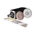
Pulse & direction stepper motor driver, supporting spontaneous pulses mode. The ADH42 stepper driver features a miniature size 42mm × 42mm × 21.5mm, wide voltage input, and advanced control algorithms for vibration suppression and low heat generation.
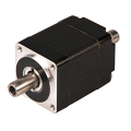
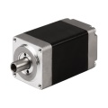
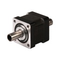
It supports standard RS232 serial command and is built with a 32-bit digital chip. The ADM42H stepper driver can be assembled for NEMA17 integrated stepper motors.
Product Advantages
- Miniature Size: Ultra-compact 42mm × 42mm × 21.5mm design.
- Dual Working Modes: Supports both Pulse & Direction and Spontaneous pulses mode.
- RS232 Support: Standard RS232 serial command interface with built-in 32-bit digital chip.
- Advanced Control: New control algorithms for vibration suppression and low heat generation.
- Wide Voltage Input: DC 12~40VDC, recommended 24VDC.
- High Output: Continuous output current 1.4A max, peak current 2.1A.
- Flexible Integration: Mountable with 42mm/39mm stepper motors.
- Protection Functions: Overvoltage, undervoltage and overcurrent protection.
- Auto Tuning: Built-in automatic matching function of motor parameters.
- Any Micro-Step: Any micro-step value can be set.
Electrical Characteristics
| Parameter | Minimum Value | Typical Value | Maximum Value | Unit |
|---|---|---|---|---|
| Supply Voltage (DC) | 12 | 24 | 40 | VDC |
| Control Signal Input Current | 7 | 10 | 16 | mA |
| Step Pulse Frequency | 0 | - | 200 | KHz |
| Insulation Resistance | 50 | - | - | MΩ |

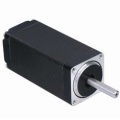
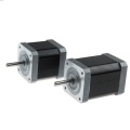
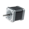
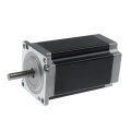
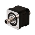
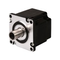
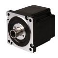
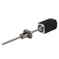
Product Images


Pin Definition
| Pin No. | Name | Description |
|---|---|---|
| 1 | PU | Pulse Control Signal Input: 5V ~ 24V, Rising Edge effective. Make sure pulse signal effective, pulse width ≥ 2μs. Add the resistance for power supply. |
| 2 | PU- | |
| 3 | DR | Direction Signal: high/low level signal 5V ~ 24V, direction signal should be at least 5μs earlier than pulse signal, High/Low level. |
| 4 | DR- | |
| 5 | EN | Enable Signal: enable/disable. If ENA connect 5V & ENA- connect low level (or Internal optocoupler on), stepper controller will turn off the current, motor in free state, no feedback even send pulses. |
| 6 | EN- | |
| 7 | AM | Alarm signal output: When overvoltage, undervoltage, phase loss, or position deviation alarms occur, the alarm signal output is effective. Maximum driving current 50mA. |
| 8 | AM- | |
| 9 | GND | Supply Voltage Ground: GND/0V |
| 10 | DC | Supply voltage: 12-40VDC, Recommend DC24V |
Wiring Diagram
Wire support common anode connection and common cathode connection, controlled by PLC or Pulse Generators.


DIP Switch Configuration
1. Set Working Current by SW1
| SW1 | Peak (A) | RMS (A) |
|---|---|---|
| Off | 1.4 | 1.0 |
| On | 2.1 | 1.5 |
2. Set Working Mode by SW2
| SW2 | Working Mode |
|---|---|
| Off | Pulse & Direction |
| On | Spontaneous Pulses |
2.1 Pulse & Direction Working Mode
Set Micro-step by SW3, SW4, SW5, SW6:

2.2 Spontaneous Pulses Working Mode
In this working mode, the PU & PU- connect to the power supply 5~24VDC and GND, make sure the stepper motor rotates instantly when power on. Please check below wiring diagram:

Set Working Speed by SW3, SW4, SW5, SW6:

Downloads & Support
- User Manual: ADH42 Stepper Motor Driver User Manual

More Information on detail, please feel free to contact me 
- Model: ADH42
- Brand: Adampower
Write Review
-
 NEMA8 Stepper Motor
$35.00
NEMA8 Stepper Motor
$35.00 -
 NEMA11 Stepper Motor
$36.00
NEMA11 Stepper Motor
$36.00 -
 NEMA14 Stepper Motor
$37.00
NEMA14 Stepper Motor
$37.00 -
 NEMA17 Stepper Motor, 42mm Stepper Motor
$36.00
NEMA17 Stepper Motor, 42mm Stepper Motor
$36.00 -
 NEMA16 Stepper Motor, 39mm Stepper Motor
$36.00
NEMA16 Stepper Motor, 39mm Stepper Motor
$36.00 -
 NEMA23 Stepper Motor, 57mm Stepper Motor
$39.00
NEMA23 Stepper Motor, 57mm Stepper Motor
$39.00 -
 NEMA6 Hollow Shaft Stepper Motor, 14mm Stepper Motor
$80.00
NEMA6 Hollow Shaft Stepper Motor, 14mm Stepper Motor
$80.00 -
 NEMA8 Hollow Shaft Stepper Motor, 20mm Stepper Motor
$35.00
NEMA8 Hollow Shaft Stepper Motor, 20mm Stepper Motor
$35.00 -
 NEMA11 Hollow Shaft Stepper Motor, 28mm Stepper Motor
$35.00
NEMA11 Hollow Shaft Stepper Motor, 28mm Stepper Motor
$35.00 -
 NEMA14 Hollow Shaft Stepper Motor
$36.00
NEMA14 Hollow Shaft Stepper Motor
$36.00 -
 NEMA17 Hollow Shaft Stepper Motor
$37.00
NEMA17 Hollow Shaft Stepper Motor
$37.00 -
 NEMA23 Hollow Shaft Stepper Motor
$40.00
NEMA23 Hollow Shaft Stepper Motor
$40.00 -
 NEMA34 Hollow Shaft Stepper Motor
$78.00
NEMA34 Hollow Shaft Stepper Motor
$78.00 -
 NEMA8 Stepper Ball Screw Linear Actuators
$126.00
NEMA8 Stepper Ball Screw Linear Actuators
$126.00 -
 NEMA8 Stepper Lead Screw Linear Actuators
$55.00
NEMA8 Stepper Lead Screw Linear Actuators
$55.00 -
 NEMA6 Stepper Ball Screw Linear Actuators
$110.00
NEMA6 Stepper Ball Screw Linear Actuators
$110.00 -
 NEMA11 Stepper Ball Screw Linear Actuators
$55.00
NEMA11 Stepper Ball Screw Linear Actuators
$55.00 -
 NEMA14 Stepper Ball Screw Linear Actuators
$55.00
NEMA14 Stepper Ball Screw Linear Actuators
$55.00 -
 NEMA17 Stepper Ball Screw Linear Actuators
$58.00
NEMA17 Stepper Ball Screw Linear Actuators
$58.00 -
 NEMA23 Stepper Ball Screw Linear Actuators
$58.00
NEMA23 Stepper Ball Screw Linear Actuators
$58.00


