


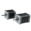
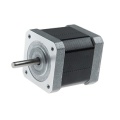
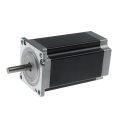
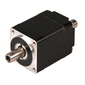
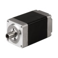
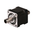
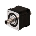
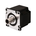
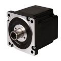
NEMA11 RS485 Stepper Motor Driver, Integrated Stepper Motor
MODBUS RTU, RS485 AR28 is a high-integrated and compact size stepper driver. It adopts standard RS485 communication protocol, can be connected with PLC, HMI, industrial computer and other upper computer with only two communication lines. Up to 32 axes of motion platform networking can be achieved with its built-in motion control commands.
AR28 can be set to 1-256 subdivisions and adopts built-in micro-subdivision technology, which can achieve high subdivision effects even under low subdivision conditions, ensuring that the motor operates with uniform step intervals and no large or small step problems.
Can be set between 1-256 subdivisions, with uniform motor step spacing; Stable output at 1/12 rpm
AR28 is designed for NEMA11/NEMA14 stepper motor, The NEMA11/NEMA14 integrated stepper motor with torque 0.06 ~ 0.35Nm:
1. Electrical Specifications
| Parameter | AR28 (5V IO) | Unit | ||
|---|---|---|---|---|
| Min | Typical | Max | ||
| Continuous Output Current | 0 | — | 1.5 | A |
| Power Supply Voltage (DC) | 15 | 24 | 28 | VDC |
| Control Signal Input Current | 6 | 10 | 16 | mA |
| Overvoltage Protection Voltage | — | 32 | — | VDC |
| Insulation Resistance | 100 | — | — | MΩ |
2. Operating Environment and Parameters
| Parameter | Specification |
|---|---|
| Cooling Method | Natural cooling or forced air cooling |
| Operating Environment - Location | Keep away from heating equipment, dust, oil mist, high humidity & strong vibration. No flammable gas or conductive dust. |
| Operating Environment - Temperature | -5℃ ~ 45℃ |
| Operating Environment - Humidity | 40 ~ 90% RH |
| Operating Environment - Vibration | 10 ~ 55Hz/0.15mm |
| Storage Temperature | -20℃ ~ 65℃ |
| Operating Altitude | ≤1000m |
| Weight | Driver section approx. 50g (excluding motor) |
3. Product Dimensions and Motor Matching
AR28 series closed-loop integrated motor basic parameters:
| Product Model | Motor Holding Torque | Shaft Length L | Motor Length L | Motor Specification |
|---|---|---|---|---|
| AR28-006IE | 0.06 Nm | 20mm | 32mm | NEMA11 |
| AR28-012IE | 0.12 Nm | 20mm | 51mm | NEMA11 |
| AR28-015IE | 0.15 Nm | 24mm | 34mm | NEMA14 |
| AR28-025IE | 0.25 Nm | 24mm | 47mm | NEMA14 |
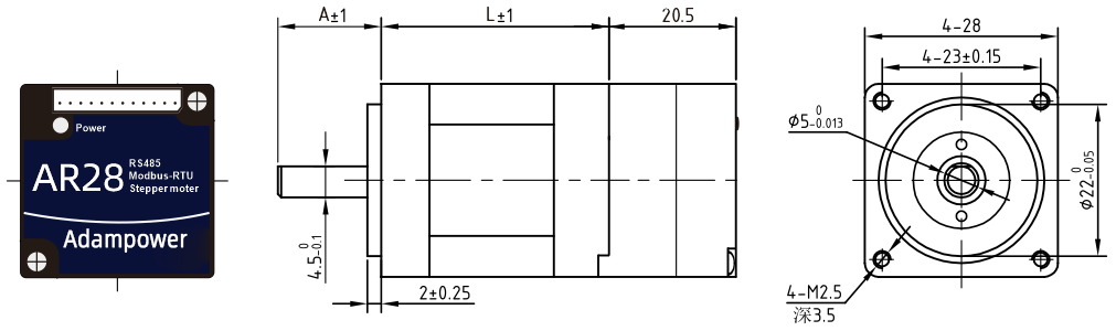
AR28-006IE / AR28-012IE Dimension Drawing (Refer to NEMA11 diagrams)
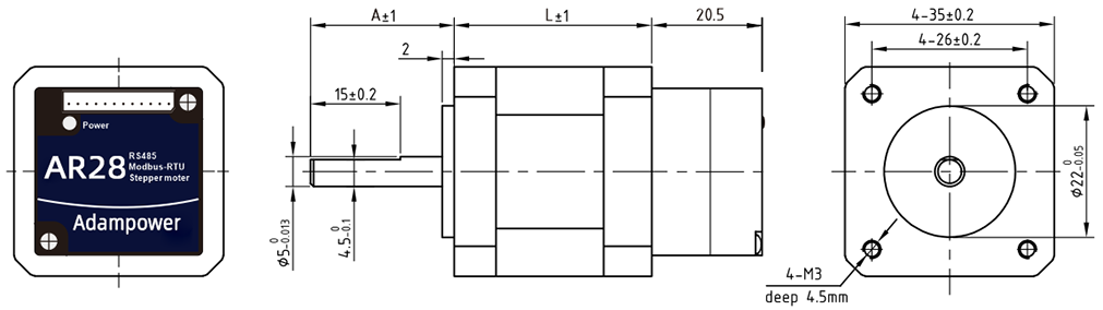
AR28-015IE / AR28-025IE Dimension Drawing (Refer to NEMA14 diagrams)
4. Heat Dissipation Precautions
The reliable operating ambient temperature for closed-loop integrated motors is typically within -5℃ ~ 45℃. Normal operating temperature is 50-80℃. If exceeding 80℃, it is necessary to evaluate whether the operating conditions and integrated motor selection are appropriate. If necessary, install a fan near the driver for forced cooling to ensure the driver operates within the reliable working temperature range.
5. LED Status Indicator
The red LED serves as both power indicator and fault display. When the driver is powered on, the LED is constantly on; when the driver is powered off, the LED is off. When a fault occurs, the indicator flashes in a 5-second cycle; when the fault is cleared by the user, the LED remains constantly on. The number of flashes within 5 seconds represents different fault information, as shown in the following table:
| No. | Flash Count | Fault Description |
|---|---|---|
| 1 | 1 | Overcurrent or inter-phase short circuit fault |
| 2 | 2 | Overvoltage fault |
| 3 | 3 | Undervoltage alarm |
| 4 | 7 | Position deviation alarm (excessive error) |
| 5 | 9 | Driver error, requires maintenance |
| 6 | 4 | Network congestion fault, requires power cycle (flashes 4 times, does not cycle) |
When a fault occurs, the driver will stop and display the corresponding fault code (item 3 network congestion has no code). The user must re-enable the driver or power cycle to clear the fault. When the driver detects a fault, it saves the latest fault to the EEPROM in a queue format. The driver can save up to 10 latest historical faults.
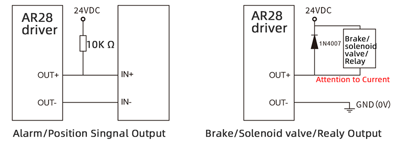
6. OUT Output Port Wiring Diagram
OUT /OUT- ports are differential output ports, allowing maximum voltage of 24V. Port instantaneous output current is 100mA, continuous output current is 50mA. To protect the port, when connecting external brakes, solenoid valves, relays, etc., freewheeling diodes must be connected across the devices to prevent port damage.
7. Zero-return Function
Zero-return function with two trajectory A and when limit signal is triggered and not:


8. Communication Protocol
Communication uses standard MODBUS protocol, supporting 0x03 (read register), 0x06 (write single register), 0x10 (16) (write multiple registers). Serial communication format: baud rate 9600~115200, 8 data bits, no parity, 1 stop bit.
AR28 Modbus Stepper Motor Controller User Manual 
Software Modbus Poll 
AdamPower Software
More Information on detail, please feel free to contact me 
- Availability: In Stock
- Model: AR11
- Brand: Adampower
Write Review
-
 NEMA8 Stepper Motor
$35.00
NEMA8 Stepper Motor
$35.00 -
 NEMA11 Stepper Motor
$36.00
NEMA11 Stepper Motor
$36.00 -
 NEMA14 Stepper Motor
$37.00
NEMA14 Stepper Motor
$37.00 -
 NEMA17 Stepper Motor, 42mm Stepper Motor
$36.00
NEMA17 Stepper Motor, 42mm Stepper Motor
$36.00 -
 NEMA16 Stepper Motor, 39mm Stepper Motor
$36.00
NEMA16 Stepper Motor, 39mm Stepper Motor
$36.00 -
 NEMA23 Stepper Motor, 57mm Stepper Motor
$39.00
NEMA23 Stepper Motor, 57mm Stepper Motor
$39.00 -
 NEMA6 Hollow Shaft Stepper Motor, 14mm Stepper Motor
$80.00
NEMA6 Hollow Shaft Stepper Motor, 14mm Stepper Motor
$80.00 -
 NEMA8 Hollow Shaft Stepper Motor, 20mm Stepper Motor
$35.00
NEMA8 Hollow Shaft Stepper Motor, 20mm Stepper Motor
$35.00 -
 NEMA11 Hollow Shaft Stepper Motor, 28mm Stepper Motor
$35.00
NEMA11 Hollow Shaft Stepper Motor, 28mm Stepper Motor
$35.00 -
 NEMA14 Hollow Shaft Stepper Motor
$36.00
NEMA14 Hollow Shaft Stepper Motor
$36.00 -
 NEMA17 Hollow Shaft Stepper Motor
$37.00
NEMA17 Hollow Shaft Stepper Motor
$37.00 -
 NEMA23 Hollow Shaft Stepper Motor
$40.00
NEMA23 Hollow Shaft Stepper Motor
$40.00 -
 NEMA34 Hollow Shaft Stepper Motor
$78.00
NEMA34 Hollow Shaft Stepper Motor
$78.00 -
 NEMA8 Stepper Ball Screw Linear Actuators
$126.00
NEMA8 Stepper Ball Screw Linear Actuators
$126.00 -
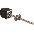
 NEMA8 Stepper Lead Screw Linear Actuators
$55.00
NEMA8 Stepper Lead Screw Linear Actuators
$55.00 -
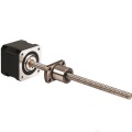
 NEMA6 Stepper Ball Screw Linear Actuators
$110.00
NEMA6 Stepper Ball Screw Linear Actuators
$110.00 -
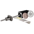
 NEMA11 Stepper Ball Screw Linear Actuators
$55.00
NEMA11 Stepper Ball Screw Linear Actuators
$55.00 -
 NEMA14 Stepper Ball Screw Linear Actuators
$55.00
NEMA14 Stepper Ball Screw Linear Actuators
$55.00 -
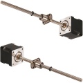
 NEMA17 Stepper Ball Screw Linear Actuators
$58.00
NEMA17 Stepper Ball Screw Linear Actuators
$58.00 -
 NEMA23 Stepper Ball Screw Linear Actuators
$58.00
NEMA23 Stepper Ball Screw Linear Actuators
$58.00


