
Adampower
![]()

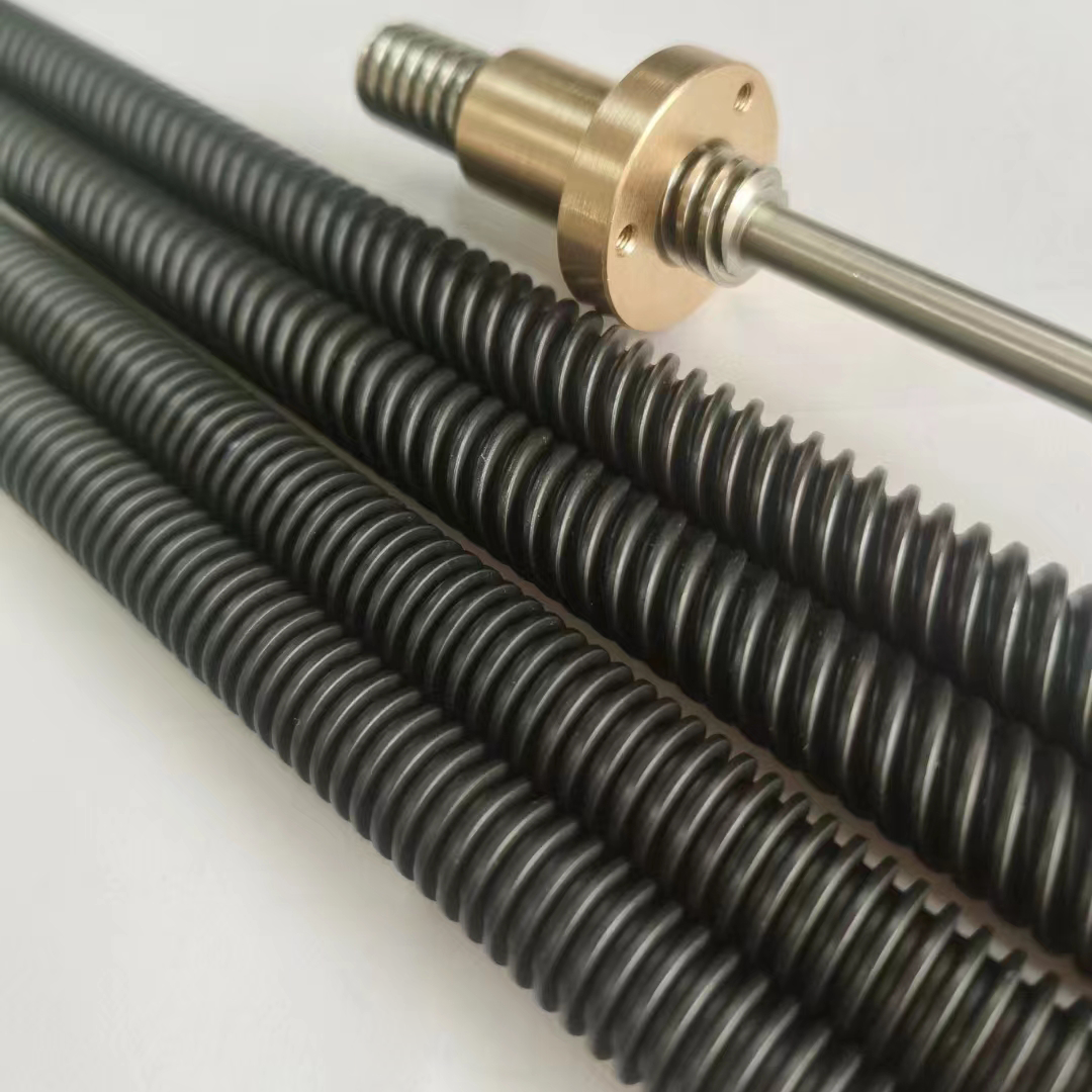
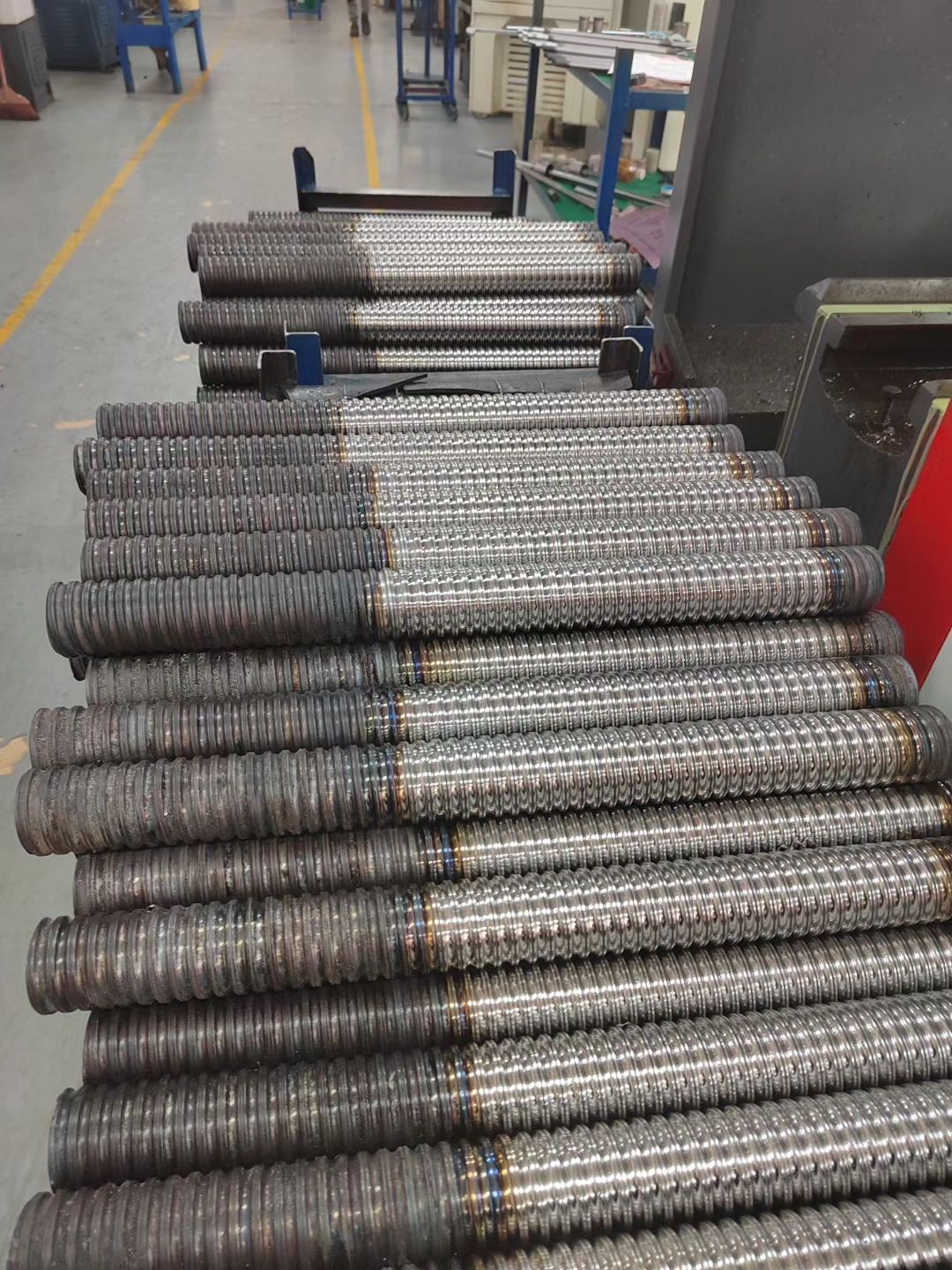
AdamPower is A high-tech enterprise specializing in the design and manufacturing of thread,
spline screw parts, and thread spline molds.has a strong scientific and technological strength
and is a university research base in the thread industry.
It has a key research project in Shanghai, including the Thread Research Cold Extrusion Tech-
nology Research Institute and Laboratory. Equipped with first-class equipment. provides
customers with design and manufacturing services for various standard and non-standard
threaded parts. has national invention patents in thread development research, multiple authoritative
awards, and important technical know-how.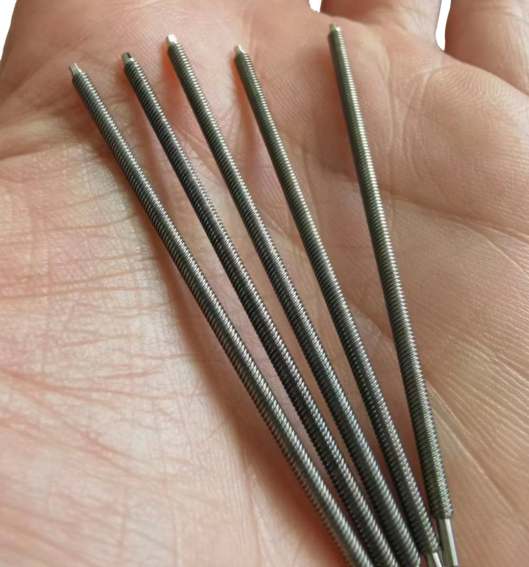
ACME US Standard Trapezoidal Thread -29°
Precision Screw Rod List:
| T3.5 | T3X0.5 | one-headed | T8 | T8x1 | one-headed |
| T3X1 P=0.5 | two-headed | T8x2 | one-headed | ||
| T3.5 | T3.5x0.6096 | one-headed | T8x4 P=2 | two-headed | |
| T3.5x1.2192 P=0.6096 | two-headed | T8x8 P=2 | four-headed | ||
| T3.5x2.43 P=1.2192 | two-headed | T8x12 P=3 | four-headed | ||
| T3.5x2.43 P=0.6096 | four-headed | T9.52 | T9.525x0.635 | one-headed | |
| T4.76 | T4.76x0.635 | one-headed | T9.525x1.2192 | one-headed | |
| T4.76x1.27 P=0.635 | two-headed | T9.525x2.43 P1.2192 | two-headed | ||
| T4.76X1.27 | one-headed | T9.525x2.54 | one-headed | ||
| T4.76x2.54P=1.27 | two-headed | T9.525x4.233P=2.116 | two-headed | ||
| T4.76x5.08 P=1.27 | four-headed | T9.525x5.08 P=2.54 | two-headed | ||
| T5 | T5X2 P=1 | two-headed | T9.525x10.16P=2.54 | four-headed | |
| T5.56 | T5.56X0.6096 | one-headed | T9.525x1.5875 | one-headed | |
| T5.56x1.2192 P=0.6096 | two-headed | T9.525x3.175 | one-headed | ||
| T5.56X1.2192 | one-headed | T9.525x3.175 P=1.5875 | two-headed | ||
| T5.56x1.5875 | one-headed | T9.525X6.35P=1.5875 | four-headed | ||
| T5.56X3.175 P=1.5875 | two-headed | T9.525x12.7P=1.5875 | eight-headed | ||
| T5.56x2.43P=1.2192 | two-headed | T9.86 | T9.86x19.05P=3.175 | six-headed | |
| T5.56x2.43 P=0.6096 | four-headed | T10 | T10x1 | one-headed | |
| T5.56X4.87P=1.2192 | four-headed | T10x2 | one-headed | ||
| T6.35 | T6.35x0.635 | one-headed | T10X2 P=1 | two-headed | |
| T6.35X1.27 P=0.635 | two-headed | T10X5 P=1 | four-headed | ||
| T6.35x1.27 | one-headed | T10×6 P=1 | six-headed | ||
| T6.35X1.5875 | one-headed | T10x4 P=2 | two-headed | ||
| T6.35X3.175 P=1.5875 | two-headed | T10x8 P=2 | four-headed | ||
| T6.35x2.43 | one-headed | T19.05 | T19.05x2.54 | one-headed | |
| T6.35x2.43P=1.2192 | two-headed | T12-T25.4 | Customized, one-headed to sixteen headed | ||
| T6.35x5.08 P=1.27 | four-headed | ||||
| T6.35x6.35 P=1.5875 | four-headed | ||||
| T6.35x12.7P=1.5875 | eight-headed | ||||
Metric trapezoidal thread -30°, Precision Screw Rod List:
| T3 | T3x0.5 | one-headed | T8 | T8x1 | one-headed |
| T3X1 P=0.5 | two-headed | T8x2 | one-headed | ||
| T3.5 | T3.5x0.5 | one-headed | T8x4 P=2 | two-headed | |
| T3.5x2 P=1 | two-headed | T8x8 P=2 | four-headed | ||
| T4 | T4x0.5 | one-headed | T9 | T9x1 | one-headed |
| T4x0.75 | one-headed | T9x2 P=1 | two-headed | ||
| T4X1 | one-headed | T9x2 | one-headed | ||
| T4X2 P=1 | two-headed | T9x4 P=2 | two-headed | ||
| T4X4 P=1 | four-headed | T9x5 P=2.5 | two-headed | ||
| T5 | T5x1 | one-headed | T9x10 P=2.5 | four-headed | |
| T5X2 P=1 | two-headed | T9.x1.5 | one-headed | ||
| T5X3 P=1 | three-headed | T9x3 P=1.5 | one-headed | ||
| T5x4 P=1 | four-headed | T9x3 P=1.5 | two-headed | ||
| T5x2 | one-headed | T9x6 P=1.5 | four-headed | ||
| T5x4 P=2 | two-headed | T9x12 P=1.5 | eight-headed | ||
| T5x1.25 | one-headed | T10 | T10x1 | one-headed | |
| T5x1.75 | one-headed | T10x1.5 | one-headed | ||
| T6 | T6X0.8 | one-headed | T10x2 P=1 | two-headed | |
| T6X1.6 P=0.8 | two-headed | T10x5 P=1 | five-headed | ||
| T6X3.2 P=0.8 | four-headed | T10x6 P=1 | six-headed | ||
| T6x1 | one-headed | T10x4 P=2 | two-headed | ||
| T6x2P=1 | two-headed | T10x8 P=2 | four-headed | ||
| T6x3 | one-headed | T10x9 P=1.5 | six-headed | ||
| T6x3 P=1 | two-headed | T12-T25 | Diaemter , Lead Screw Customized | one-headed to sixteen headed can be customized | |
| T6X4 P=2 | two-headed | ||||
| T6X6P=1 | six-headed | ||||
| T6X12 P=1.5 | eight-headed |
Mini Screw, tiny Screw even Fingertip screw can be customized as requirement.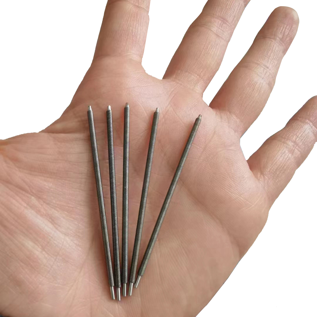
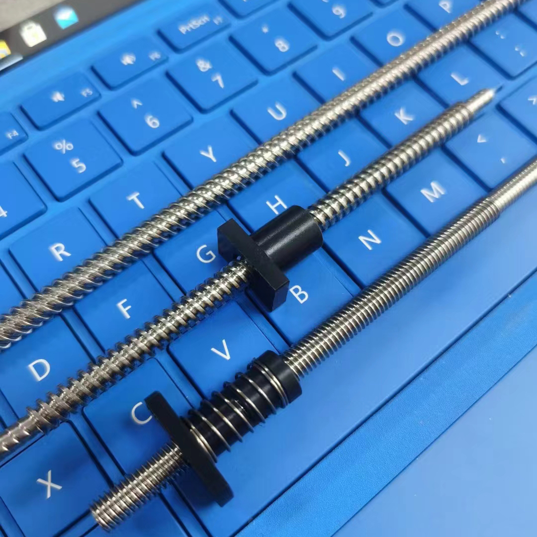
Planetary Screws: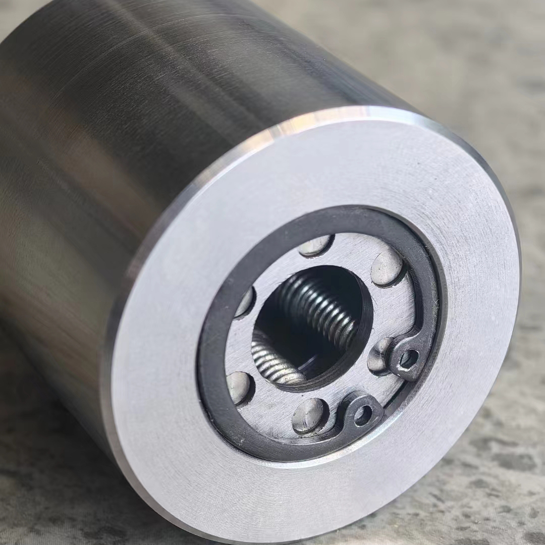
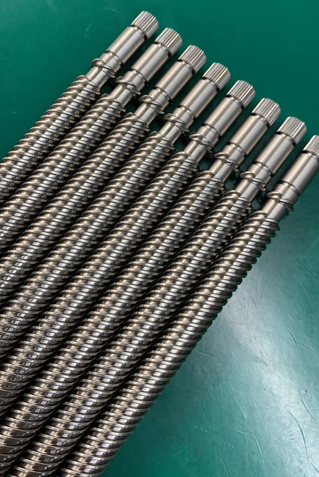
Customized Big Size Screw, Long Lead Travel, Bigger Diameters and so on.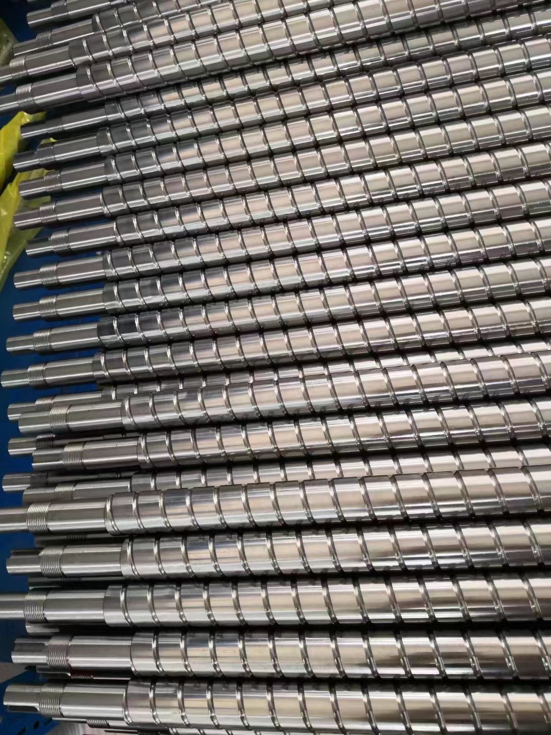
More Information on detail, please feel free to contact me

| Step Accuracy: | ±5% | Resistance Accuracy: | ±10% |
|---|---|---|---|
| Inductance Accuracy: | ±20% | Temperature Rise: | 80°C MAX |
| Ambient Temperature Range: | -20°C~ 50°C | Storage Temperature Range: | -30°C~ 60°C |
| Insulation Resistance: | 100M Ω MIN. 500V DC | Dielectric Strength: | 500V AC 1min |
| Radial Play: | 0.02mm MAX. (450g Load) | End Play: | 0.08mm MAX. (450g Load) |
| Max. Radial Force: | 20N | Max. Axial Force: | 2N |
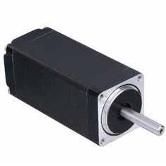
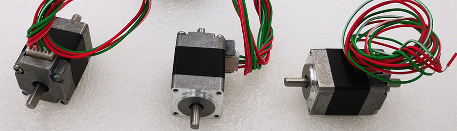
NEMA8 Stepper Motor, 1.8° step angle stepper motor
Electrical Specifications:
|
Model No. |
Step Angle |
Motor Length (mm) |
Rated voltage (v) |
Rated Current (A) |
Phase Resistance (Ω) |
Phase Indutance (Mh) |
Holding Torque(MIN) N.cm |
Detent Toruue(MAX) N.cm |
Motor Torque (g.cm2) |
Lead Wire |
Motor Weight (g) |
| 8HS2402 | 1.8 | 28 | 4.6 | 0.2 | 23 | 8.2 | 1.4 | 0.2 | 2.5 | 4 | 50 |
| 8HS2406 | 1.8 | 28 | 1.92 | 0.6 | 3.2 | 0.9 | 1.4 | 0.2 | 2.5 | 4 | 50 |
| 8HS3402 | 1.8 | 33 | 5 | 0.2 | 25 | 8.4 | 1.8 | 0.3 | 3.2 | 4 | 70 |
| 8HS3406 | 1.8 | 33 | 3.9 | 0.6 | 6.5 | 1.7 | 1.8 | 0.3 | 2 | 4 | 60 |
| 8HS4406 | 1.8 | 40 | 3.48 | 0.6 | 5.8 | 1.6 | 2.6 | 0.5 | 4.5 | 4 | 82 |
| 8HS4408 | 1.8 | 40 | 4.32 | 0.8 | 5.4 | 1.5 | 3 | 0.5 | 3.6 | 4 | 80 |
Mechanical Dimensions and Wiring Diagram: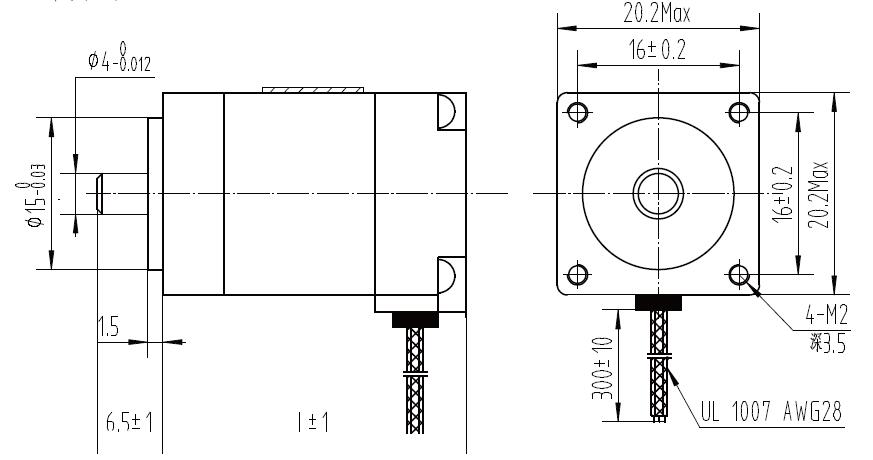
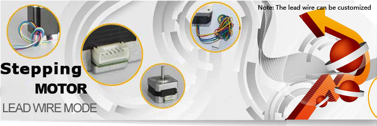
Lead Wire Mode Options:
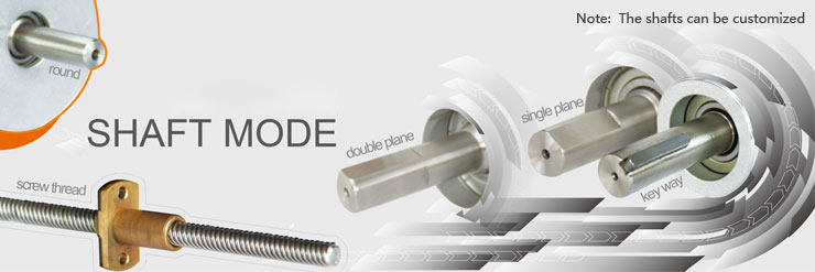
Shaft Mode can be customized as the requirement.
More Information on detail, please feel free to contact me

Size:
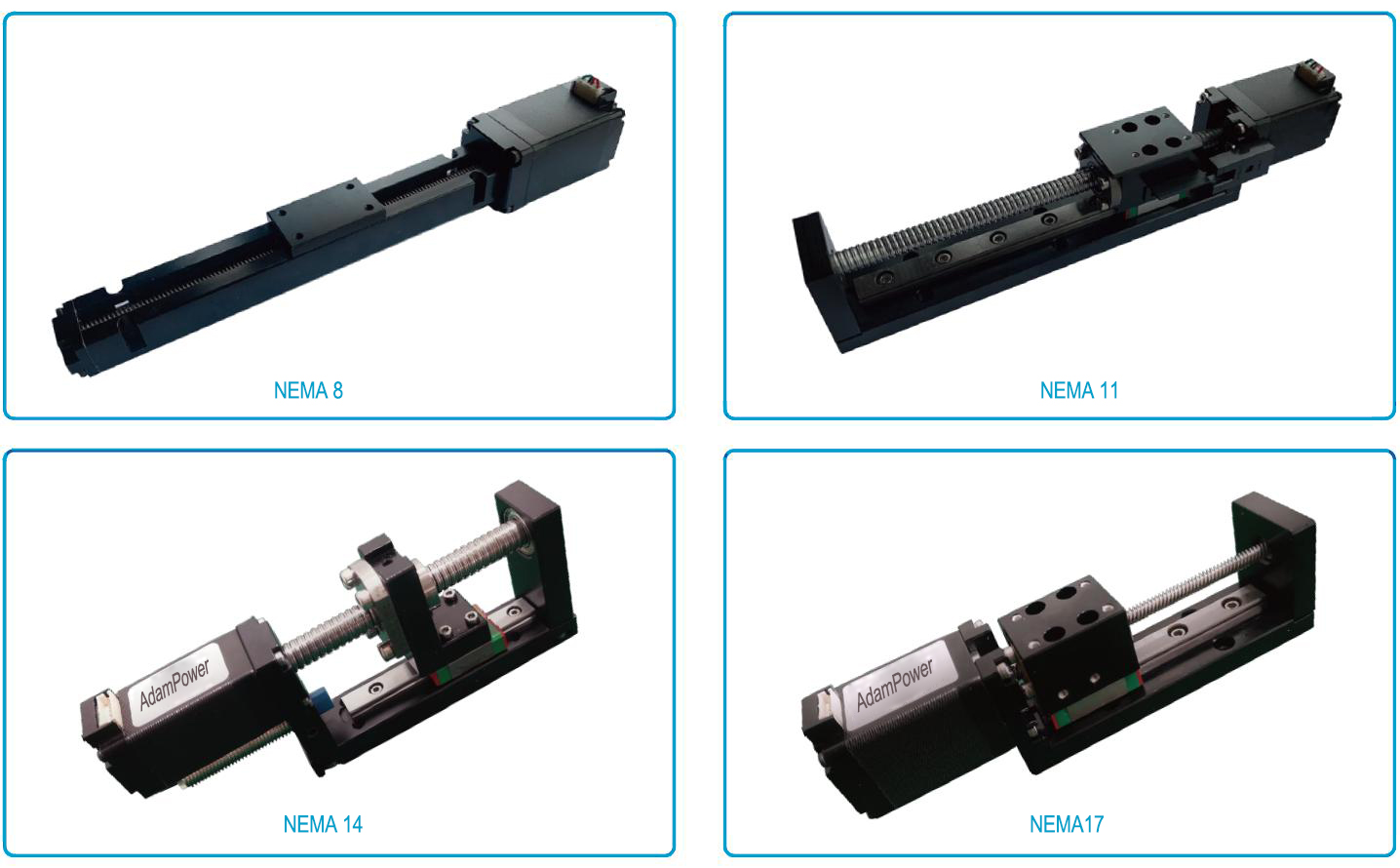
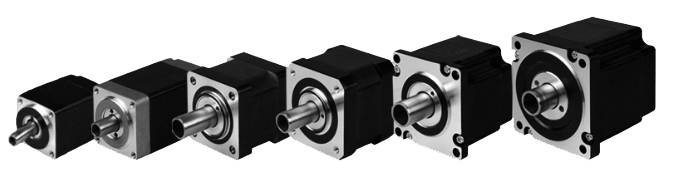
NEMA6, NEMA8, NEMA11, NEMA14, NEMA17, NEMA23, NEMA23, NEMA34
14mm, 20mm, 28mm, 35mm, 42mm, 57mm, 60mm, 86mm
Stepper
0.001524mm~0.16mm
Performance
Maximum thrust up to 240kg, low temperature rise, low vibration, low noise,
long life (up to 5 million cycles), and high positioning accuracy (up to ±0.005 mm)
Application
Medical diagnostic equipment, life science instruments, robots, optical equipment,
analytical instruments, semiconductor equipment, communication equipment, automation equipment
NEMA6 Lead Screw Linear Actuators
Linear Module, Linear Slider
| Motor Type | Bipolar stepper |
| Step Angle | 1.8° |
| Voltage (V) | 2.5 / 6.3 |
| Current (A) | 0.5 |
| Resistance (Ohms) | 5.1 / 12.5 |
| Inductance (mH) | 1.5 / 4.5 |
| Lead Wires | 4 |
| Motor Length (mm) | 30 / 42 |
| Stroke (mm) | 30 / 60 / 90 |
| Ambient Temperature | -20℃ ~ 50℃ |
| Temperature Rise | 80K Max. |
| Dielectric Strength | 1mA Max. @ 500V, 1KHz, 1Sec. |
| Insulation Resistance | 100MΩ Min. @500Vdc |
Motor Characteristics:
| Motor | Phase voltage [V] | Phase Current [A] | Phase Resistance [Ω] | Phase Inductance [mH] | Lenght [mm] | Number of lead Wires | Weight [g] |
|---|---|---|---|---|---|---|---|
| 0632 | 6.6 | 0.3 | 22 | 4.5 | 32 | 4 | 60 |
Available Lead Screw and Travel per Step:
Diameter (mm) | Lead (mm) | Step (mm) |
3.5 | 0.3048 | 0.001524 |
3.5 | 0.6096 | 0.003048 |
3.5 | 1 | 0.005 |
3.5 | 1.2192 | 0.006096 |
3.5 | 2 | 0.01 |
3.5 | 4 | 0.02 |
3.5 | 8 | 0.04 |
3.5 | Customized size | |
NEMA6 Linear Actuator outline drawing:
| Stroke B (mm) | 20 | 40 | 60 | 80 | 100 | 120 | 150 | Size can be Customized |
| Dimension A (mm) | 60 | 80 | 100 | 120 | 140 | 160 | 190 |
More Information on detail, please feel free to contact me

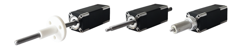
NEMA6 Stepper Lead Screw Linear Actuators
The NEMA 6 is our smallest hybrid linear actuators.
This compact unit can be integrated into various
Applications to provide precise linear positioning while
occupying less than 1 in2 of mouting footprint and
providing up to 44.5N of continuous thrust.
The Working Type for the Different Application Demand:
E: External Linear
N: Non-captive
K: Kaptive
Motor Characteristics:
| Motor Code | Voltage (V) | Current (A) | Resistance (Ω) | Inductance (mH) | Weight (g) | Lead Wire No | Length (mm) |
| 6-30 | 6.6 | 0.3 | 22 | 3.6 | 50 | 4 | 30 |
| 6-28 | 2.45 | 0.5 | 4.9 | 1.5 | 48 | 4 | 28 |
| 6-38 | 5.5 | 0.5 | 11 | 2 | 55 | 4 | 38 |
Available Lead Screw and Travel per Step:
| Lead Code | Screw Dia. (inch) | Screw Dia. (mm) | Lead (inch) | Lead (mm) | Travel Per Step @ 1.8 deg (mm) |
| AF | 0.138 | 3.5 | 0.012 | 0.3048 | 0.0015 |
| AA | 0.138 | 3.5 | 0.024 | 0.6096 | 0.003 |
| B | 0.138 | 3.5 | 0.048 | 1.2192 | 0.0061 |
| G | 0.138 | 3.5 | 0.079 | 2 | 0.01 |
| M | 0.138 | 3.5 | 0.158 | 4 | 0.02 |
| T | 0.138 | 3.5 | 0.315 | 8 | 0.04 |
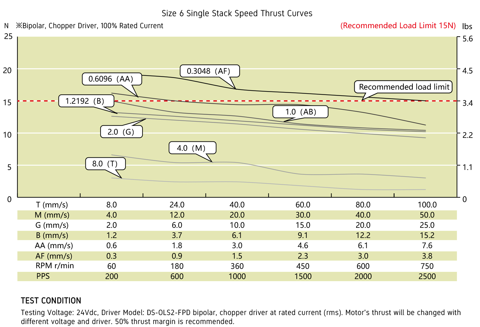
NEMA 6 Stepper Lead Screw Linear Actuators (External Type):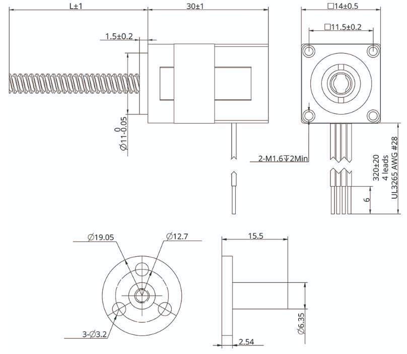
NEMA6 Stepper Lead Screw Linear Actuators Speed Thrust Curves:
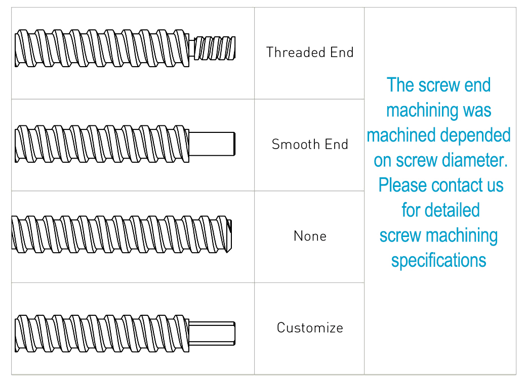
Options for screw end machining:
Catalog for download 
More Information on detail, please feel free to contact me

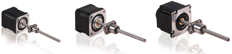
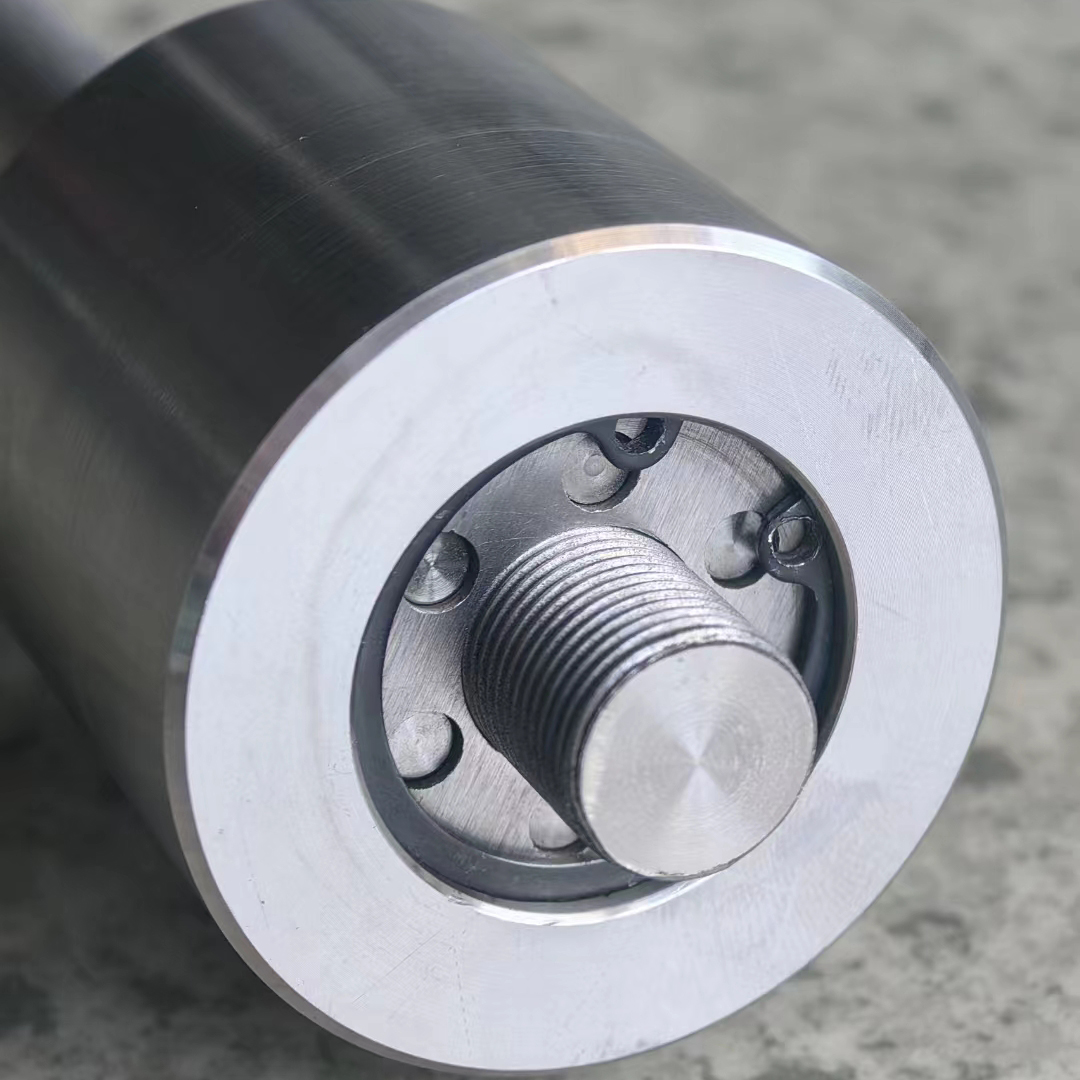
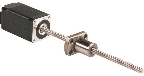
NEMA6 Stepper Ball Screw Linear Actuators
These actuators are external types have 6 different sizes, from 20mm to 57mm. From 0.005mm/
step to 0.1mm/step, variety of resolution for options available. Maximum thrust can reach 1600N.
Encoder option is available for whole Series
| Motor size | NEMA8 | NEMA11 | NEMA14 | NEMA17 | NEMA23 | ||||
| Dia. Lead | Φ4 | Φ5 | Φ6 | Φ6 | Φ8 | Φ6 | Φ8 | Φ10 | Φ12 |
| 1.0 mm | * | * | * | * | * | * | |||
| 2.0 mm | * | * | * | * | * | * | * | * | |
| 2.5 mm | * | * | |||||||
| 4.0 mm | * | * | |||||||
| 5.0 mm | * | * | * | ||||||
| 6.0 mm | * | * | * | ||||||
| 8.0 mm | * | * | |||||||
| 10.0 mm | * | * | * | * | * | * | * | ||
| 12.0 mm | * | * | |||||||
| 15.0 mm | * | ||||||||
| 20.0 mm | * | ||||||||
NEMA6 Stepper Ball Screw Linear Actuators
Motor Characteristics:
| Motor Code | Voltage (V) | Current (A) | Resistance (Ω) | Inductance (mH) | Weight (g) | Lead Wire No | Length (mm) |
| 6E2103 | 6.6 | 0.3 | 22 | 3.6 | 51 | 4 | 30 |
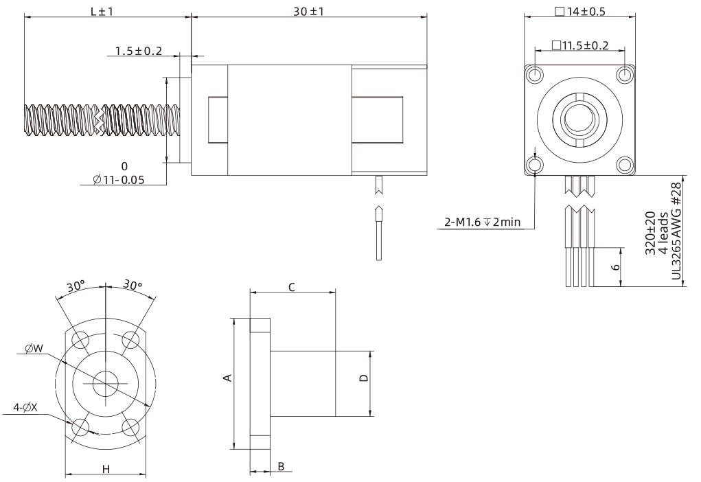
| Ball screw type | SR0401 | SR0402 |
| Ball Diameter | Ф0.8 | Ф0.8 |
| Number of thread | 1 | |
| Thread direction | Right | |
| Shaft root dia. | Ф3.3 | |
| Number of circuit | 3.7×1 | 2.7×1 |
| Shat, nut material | SCM415H | |
| Surface hardness | HRC58~62 | |
| Anti-rust treatment | Anti-rust oil | |
| Nut size | A | B | C | D | H | W | X | Grade | Position accuracy | Total run out | Axial play | Dynamic load(N) | Static load(N) |
| SR0401 | 23 | 4 | 17 | 11 | 15 | 17 | 3.4 | C7 | ±0.05 | 0.12 | 0.02 | 560 | 790 |
| SR0402 | 23 | 4 | 19 | 11 | 15 | 17 | 3.4 | C7 | ±0.05 | 0.12 | 0.02 | 420 | 570 |
NEMA 6 Ball Screw Liner Stepper Motor Performance Curves: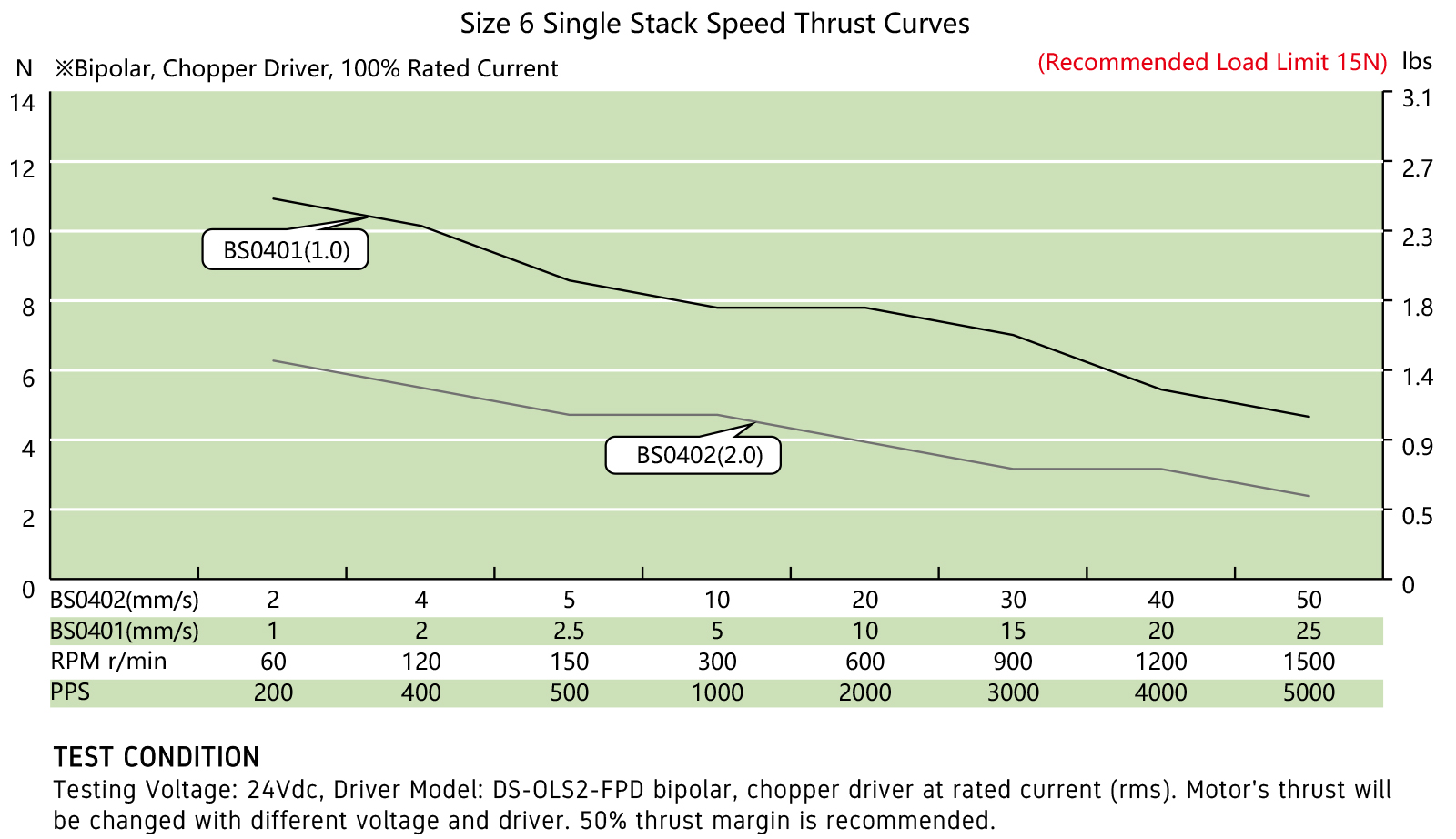
Options for screw end machining:
Catalog for download
More Information on detail, please feel free to contact me

| Step Accuracy: | ±5% | Resistance Accuracy: | ±10% |
|---|---|---|---|
| Inductance Accuracy: | ±20% | Temperature Rise: | 80°C MAX |
| Ambient Temperature Range: | -20°C~ 50°C | Storage Temperature Range: | -30°C~ 60°C |
| Insulation Resistance: | 100M Ω MIN. 500V DC | Dielectric Strength: | 500V AC 1min |
| Radial Play: | 0.02mm MAX. (450g Load) | End Play: | 0.08mm MAX. (450g Load) |
| Max. Radial Force: | 20N | Max. Axial Force: | 2N |
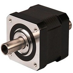
NEMA17 Hollow Shaft Stepper Motor
Electrical Specifications:
Model No. | Step Angle | Motor Length (mm) | Rated voltage (v) | Rated Current (A) | Phase Resistance (Ω) | Phase Indutance (Mh) | Holding Torque(MIN) N.cm | Weight (KG) | Inertia (g*cm2) |
| 17HS1235 | 1.8 | 35 | 3.8 | 1.2 | 2.1 | 4.2 | 7 | 0.24 | 35 |
| 17HS2049 | 1.8 | 49 | 2.5 | 2.0 | 1.35 | 3.2 | 48 | 0.36 | 77 |
Mechanical Dimensions and Wiring Diagram: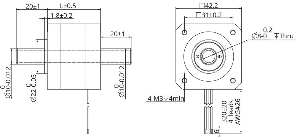
Torque Performance Curve: 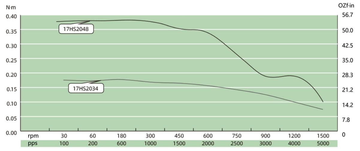
Lead Wire Mode Options:
More Information on detail, please feel free to contact me

| Step Accuracy: | ±5% | Resistance Accuracy: | ±10% |
|---|---|---|---|
| Inductance Accuracy: | ±20% | Temperature Rise: | 80°C MAX |
| Ambient Temperature Range: | -20°C~ 50°C | Storage Temperature Range: | -30°C~ 60°C |
| Insulation Resistance: | 100M Ω MIN. 500V DC | Dielectric Strength: | 500V AC 1min |
| Radial Play: | 0.02mm MAX. (450g Load) | End Play: | 0.08mm MAX. (450g Load) |
| Max. Radial Force: | 20N | Max. Axial Force: | 2N |
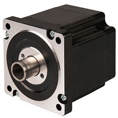
NEMA34 Hollow Shaft Stepper Motor
Electrical Specifications:
Model No. | Step Angle | Motor Length (mm) | Rated Current (A) | Phase Resistance (Ω) | Phase Indutance (Mh) | Holding Torque(MIN) N.m | Rated Voltage v | Detent Torque (N.m) |
| 34HS2076 | 1.8 | 76.0 | 3.0 | 1.9 | 19 | 4.5 | 5.7 | 0.095 |
Mechanical Dimensions and Wiring Diagram: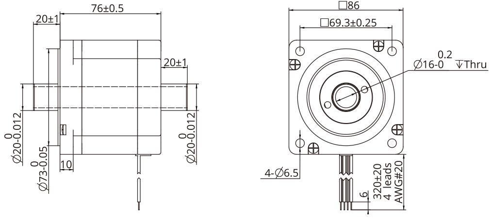
Torque Performance Curve: 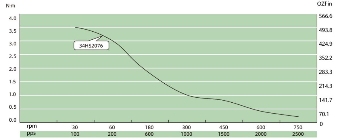
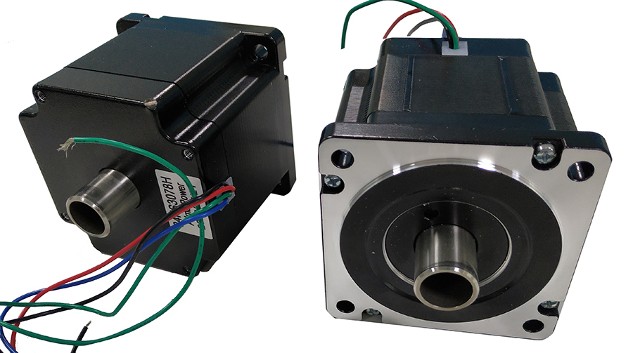
Lead Wire Mode Options:
More Information on detail, please feel free to contact me

NEMA8 Stepper Ball Screw Linear Actuators
These actuators are external types have 5 different sizes, from 20mm to 57mm. From 0.005mm/
step to 0.1mm/step, variety of resolution for options available. Maximum thrust can reach 1600N.
Encoder option is available for whole Series
| Motor size | NEMA8 | NEMA11 | NEMA14 | NEMA17 | NEMA23 | ||||
| Dia. Lead | Φ4 | Φ5 | Φ6 | Φ6 | Φ8 | Φ6 | Φ8 | Φ10 | Φ12 |
| 1.0 mm | * | * | * | * | * | * | |||
| 2.0 mm | * | * | * | * | * | * | * | * | |
| 2.5 mm | * | * | |||||||
| 4.0 mm | * | * | |||||||
| 5.0 mm | * | * | * | ||||||
| 6.0 mm | * | * | * | ||||||
| 8.0 mm | * | * | |||||||
| 10.0 mm | * | * | * | * | * | * | * | ||
| 12.0 mm | * | * | |||||||
| 15.0 mm | * | ||||||||
| 20.0 mm | * | ||||||||
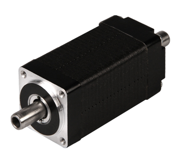
NEMA8 Stepper Ball Screw Linear Actuators
Motor Characteristics:
| Motor Code | Voltage (V) | Current (A) | Resistance (Ω) | Inductance (mH) | Weight (g) | Lead Wire No | Length (mm) |
| 8E2004 | 3.5 | 0.4 | 8.8 | 2.8 | 51 | 4 | 20 |
| 8E2105 | 2.55 | 0.5 | 5.1 | 1.5 | 74 | 4 | 27.2 |
| 8E2205 | 4.4 | 0.5 | 8.8 | 2.7 | 74 | 4 | 38.1 |
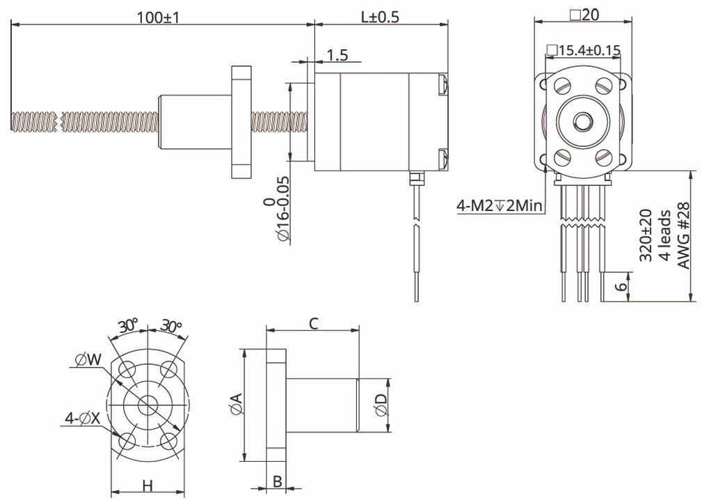
| Ball screw type | SR0401 | SR0402 |
| Ball Diameter | Ф0.8 | Ф0.8 |
| Number of thread | 1 | |
| Thread direction | Right | |
| Shaft root dia. | Ф3.3 | |
| Number of circuit | 3.7×1 | 2.7×1 |
| Shat, nut material | SCM415H | |
| Surface hardness | HRC58~62 | |
| Anti-rust treatment | Anti-rust oil | |
| Nut size | A | B | C | D | H | W | X | Grade | Position accuracy | Total run out | Axial play | Dynamic load(N) | Static load(N) |
| SR0401 | 23 | 4 | 17 | 11 | 15 | 17 | 3.4 | C7 | ±0.05 | 0.12 | 0.02 | 560 | 790 |
| SR0402 | 23 | 4 | 19 | 11 | 15 | 17 | 3.4 | C7 | ±0.05 | 0.12 | 0.02 | 420 | 570 |
NEMA 8 Ball Screw Liner Stepper Motor Performance Curves: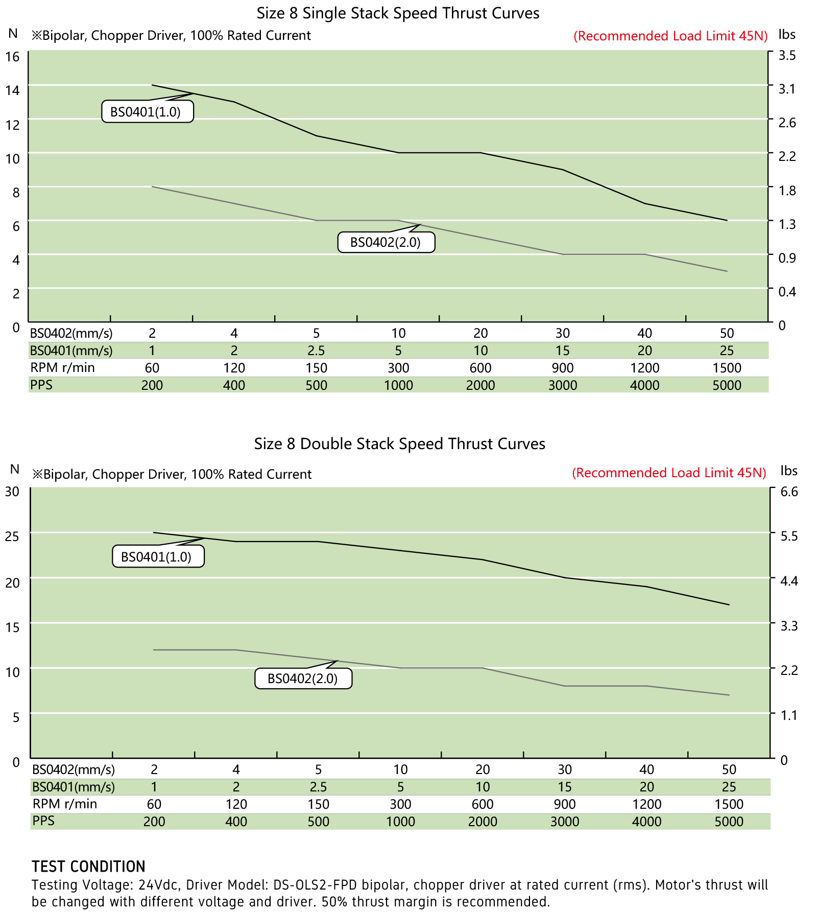
Options for screw end machining:
Catalog for download
More Information on detail, please feel free to contact me

| Step Accuracy: | ±5% | Resistance Accuracy: | ±10% |
|---|---|---|---|
| Inductance Accuracy: | ±20% | Temperature Rise: | 80°C MAX |
| Ambient Temperature Range: | -20°C~ 50°C | Storage Temperature Range: | -30°C~ 60°C |
| Insulation Resistance: | 100M Ω MIN. 500V DC | Dielectric Strength: | 500V AC 1min |
| Radial Play: | 0.02mm MAX. (450g Load) | End Play: | 0.08mm MAX. (450g Load) |
| Max. Radial Force: | 20N | Max. Axial Force: | 2N |
NEMA8 Hollow Shaft Stepper Motor
Electrical Specifications:
Model No. | Step Angle | Motor Length (mm) | Rated voltage (v) | Rated Current (A) | Phase Resistance (Ω) | Phase Indutance (Mh) | Holding Torque(MIN) N.cm | Detent Toruue(MAX) N.cm | Motor Torque (g.cm2) | Lead Wire | Motor Weight (g) |
| 8HS2028 | 1.8 | 27.2 | 2.55 | 0.5 | 5.1 | 1.5 | 1.4 | 0.2 | 2.5 | 4 | 50 |
| 8HS2038 | 1.8 | 28.1 | 4.4 | 0.5 | 8.8 | 2.7 | 2.0 | 0.2 | 4.5 | 4 | 70 |
Mechanical Dimensions and Wiring Diagram: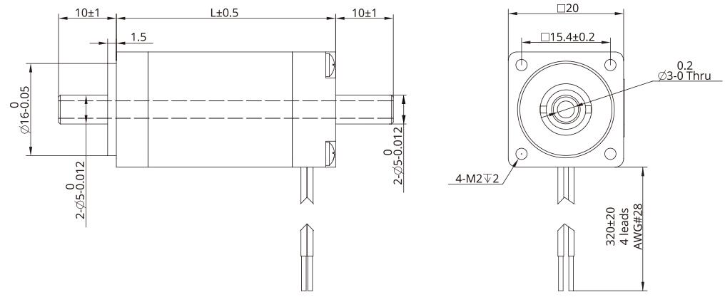
Torque Performance Curve: 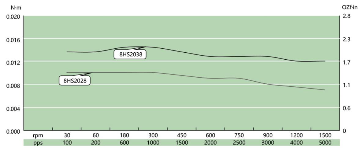
Lead Wire Mode Options:
More Information on detail, please feel free to contact me

| Step Accuracy: | ±5% | Resistance Accuracy: | ±10% |
|---|---|---|---|
| Inductance Accuracy: | ±20% | Temperature Rise: | 80°C MAX |
| Ambient Temperature Range: | -20°C~ 50°C | Storage Temperature Range: | -30°C~ 60°C |
| Insulation Resistance: | 100M Ω MIN. 500V DC | Dielectric Strength: | 500V AC 1min |
| Radial Play: | 0.02mm MAX. (450g Load) | End Play: | 0.08mm MAX. (450g Load) |
| Max. Radial Force: | 20N | Max. Axial Force: | 2N |
NEMA14 Hollow Shaft Stepper Motor
Electrical Specifications:
Model No. | Step Angle | Motor Length (mm) | Rated voltage (v) | Rated Current (A) | Phase Resistance (Ω) | Phase Indutance (Mh) | Holding Torque(MIN) N.cm | Detent Toruue(MAX) N.cm | Lead Wire |
| 14HS2033 | 1.8 | 33.6 | 3.5 | 1.0 | 3.5 | 3.6 | 19 | 0.8 | 4 |
| 14HS2045 | 1.8 | 45.6 | 6.0 | 1.0 | 6.0 | 7.2 | 36 | 1.3 | 4 |
Mechanical Dimensions and Wiring Diagram: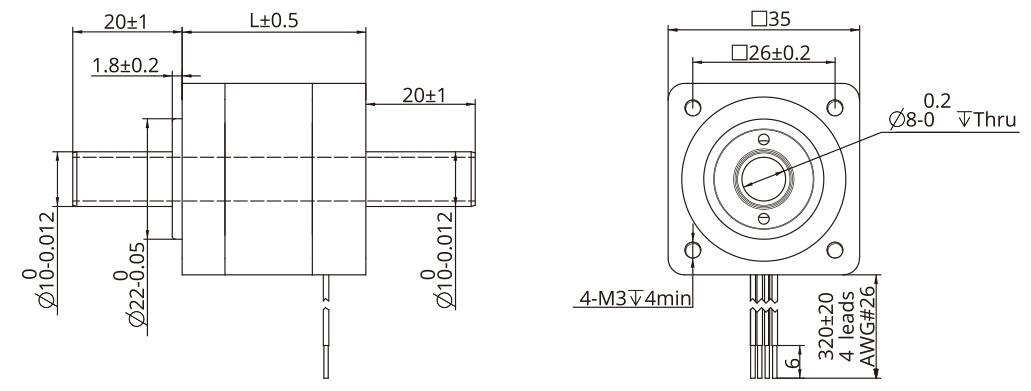
Torque Performance Curve: 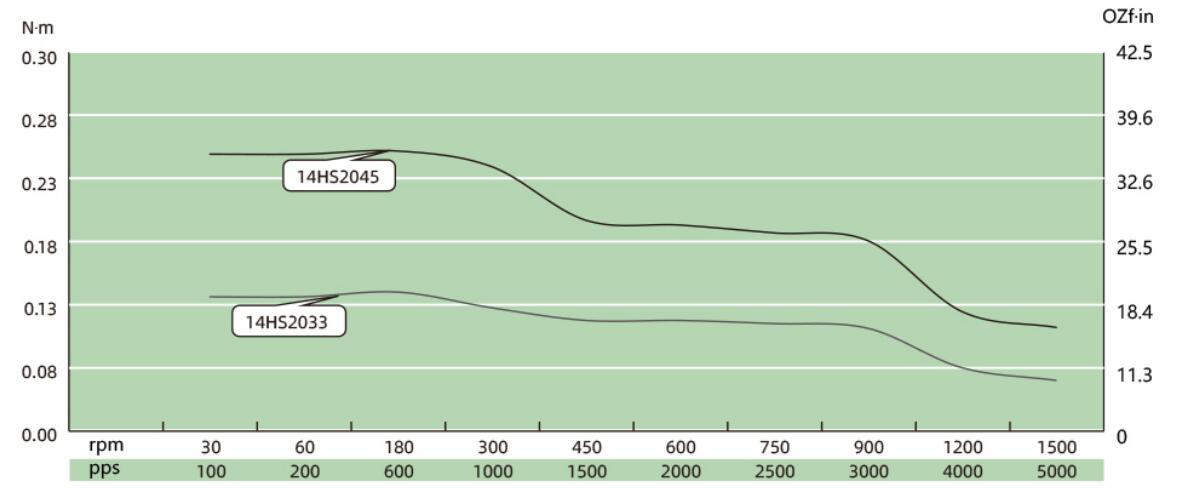
Lead Wire Mode Options:
More Information on detail, please feel free to contact me

| Step Accuracy: | ±5% | Resistance Accuracy: | ±10% |
|---|---|---|---|
| Inductance Accuracy: | ±20% | Temperature Rise: | 80°C MAX |
| Ambient Temperature Range: | -20°C~ 50°C | Storage Temperature Range: | -30°C~ 60°C |
| Insulation Resistance: | 100M Ω MIN. 500V DC | Dielectric Strength: | 500V AC 1min |
| Radial Play: | 0.02mm MAX. (450g Load) | End Play: | 0.08mm MAX. (450g Load) |
| Max. Radial Force: | 20N | Max. Axial Force: | 2N |
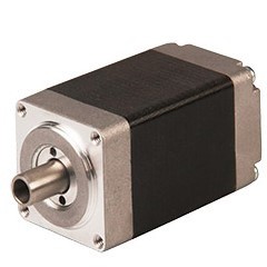
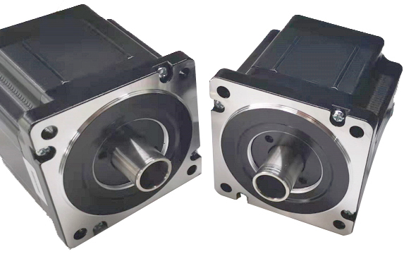
NEMA11 Hollow Shaft Stepper Motor
Electrical Specifications:
Model No. | Step Angle | Motor Length (mm) | Rated voltage (v) | Rated Current (A) | Phase Resistance (Ω) | Phase Indutance (Mh) | Holding Torque(MIN) N.cm | Detent Toruue(MAX) N.cm | Lead Wire |
| 11HS2033 | 1.8 | 33.5 | 2.1 | 1.0 | 2.1 | 1.5 | 5.3 | 0.4 | 4 |
| 11HS2045 | 1.8 | 45.0 | 4.1 | 1.0 | 4.1 | 4.0 | 11.7 | 0.4 | 4 |
Mechanical Dimensions and Wiring Diagram: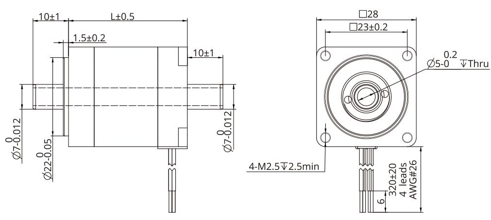
Torque Performance Curve: 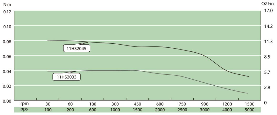
Lead Wire Mode Options:
More Information on detail, please feel free to contact me

| Step Accuracy: | ±5% | Resistance Accuracy: | ±10% |
|---|---|---|---|
| Inductance Accuracy: | ±20% | Temperature Rise: | 80°C MAX |
| Ambient Temperature Range: | -20°C~ 50°C | Storage Temperature Range: | -30°C~ 60°C |
| Insulation Resistance: | 100M Ω MIN. 500V DC | Dielectric Strength: | 500V AC 1min |
| Radial Play: | 0.02mm MAX. (450g Load) | End Play: | 0.08mm MAX. (450g Load) |
| Max. Radial Force: | 20N | Max. Axial Force: | 2N |
NEMA23 Hollow Shaft Stepper Motor
Electrical Specifications:
Model No. | Step Angle | Motor Length (mm) | Rated Current (A) | Phase Resistance (Ω) | Phase Indutance (Mh) | Holding Torque(MIN) N.m | Lead Wire | Weight (Kg) |
| 23HS45 | 1.8 | 45 | 2.0 | 1.75 | 4.1 | 0.8 | 4 | 0.6 |
| 23HS65 | 1.8 | 65 | 4.0 | 0.7 | 2.0 | 2.1 | 4 | 0.8 |
| 23HS76 | 1.8 | 76 | 4.0 | 0.65 | 2.5 | 2.0 | 4 | 1.1 |
Mechanical Dimensions and Wiring Diagram: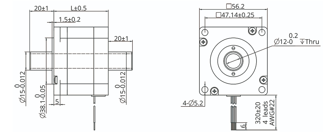
Torque Performance Curve: 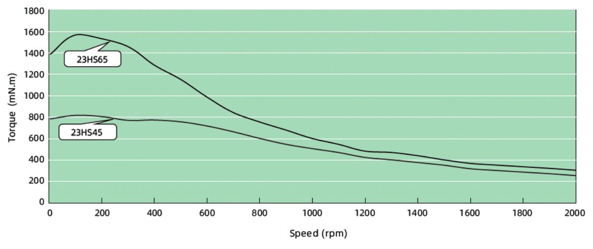
Lead Wire Mode Options:
More Information on detail, please feel free to contact me

Size:
NEMA6, NEMA8, NEMA11, NEMA14, NEMA17, NEMA23, NEMA23, NEMA34
14mm, 20mm, 28mm, 35mm, 42mm, 57mm, 60mm, 86mm
Stepper
0.001524mm~0.16mm
Performance
Maximum thrust up to 240kg, low temperature rise, low vibration, low noise,
long life (up to 5 million cycles), and high positioning accuracy (up to ±0.005 mm)
Application
Medical diagnostic equipment, life science instruments, robots, optical equipment,
analytical instruments, semiconductor equipment, communication equipment, automation equipment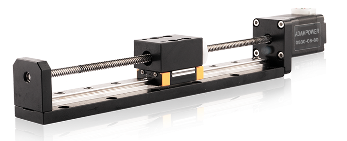
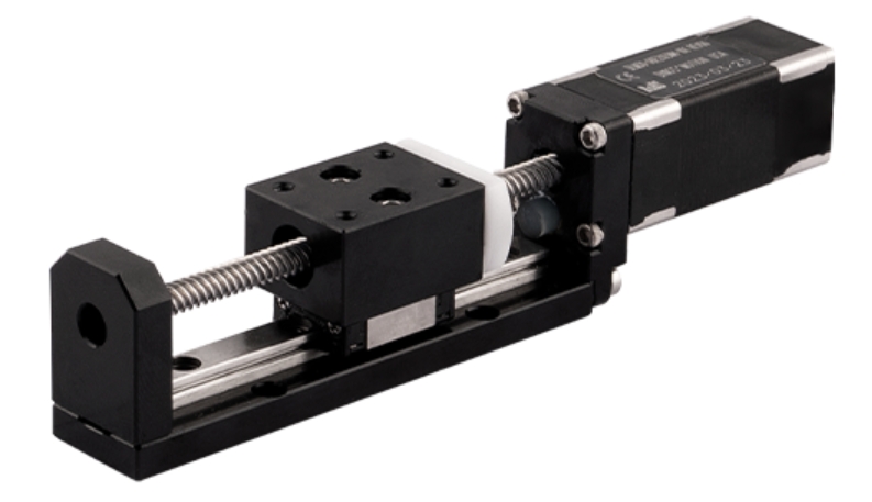
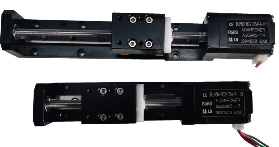
NEMA8 Lead Screw Linear Actuators
Linear Module, Linear Slider
| Motor Type | Bipolar stepper |
| Step Angle | 1.8° |
| Voltage (V) | 2.5 / 6.3 |
| Current (A) | 0.5 |
| Resistance (Ohms) | 5.1 / 12.5 |
| Inductance (mH) | 1.5 / 4.5 |
| Lead Wires | 4 |
| Motor Length (mm) | 30 / 42 |
| Stroke (mm) | 30 / 60 / 90 |
| Ambient Temperature | -20℃ ~ 50℃ |
| Temperature Rise | 80K Max. |
| Dielectric Strength | 1mA Max. @ 500V, 1KHz, 1Sec. |
| Insulation Resistance | 100MΩ Min. @500Vdc |
Motor Characteristics:
| Motor | Phase voltage [V] | Phase Current [A] | Phase Resistance [Ω] | Phase Inductance [mH] | Lenght [mm] | Number of lead Wires |
|---|---|---|---|---|---|---|
| 08S | 2.5 | 0.5 | 5.1 | 1.5 | 27.2 | 4 |
| 08D | 4.4 | 0.5 | 8.8 | 2.7 | 38.1 | 4 |
0830/0842:
Motor | Voltage/ Phase (V) | Current/ Phase (A) | Resistance/ Phase (Ω) | Inductance/ Phase (mH) | Number of Lead Wires | Rotor Inertia (g.cm2) | Motor Weight (g) | Motor Length L (mm) |
0830 | 2.5 | 0.5 | 5.1 | 1.5 | 4 | 2 | 50 | 30 |
0842 | 6.3 | 0.5 | 12.5 | 4.5 | 4 | 3 | 80 | 42 |
Available Lead Screw and Travel per Step:
Diameter (mm) | Lead (mm) | Step (mm) | Power off self-locking force (N) |
3.5 | 0.3048 | 0.001524 | 80 |
3.5 | 1 | 0.005 | 40 |
3.5 | 2 | 0.01 | 10 |
3.5 | 4 | 0.02 | 1 |
3.5 | 8 | 0.04 | 0 |
3.5 | Customized size | ||
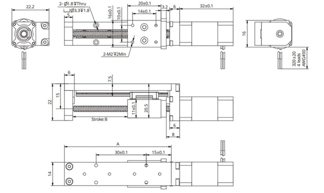
08S/08D Linear Actuator outline drawing:

| Stroke B (mm) | 20 | 40 | 60 | 80 | 100 | 120 | 150 | Size can be Customized |
| Dimension A (mm) | 60 | 80 | 100 | 120 | 140 | 160 | 190 |
0830/0842 Linear Actuator outline drawing:
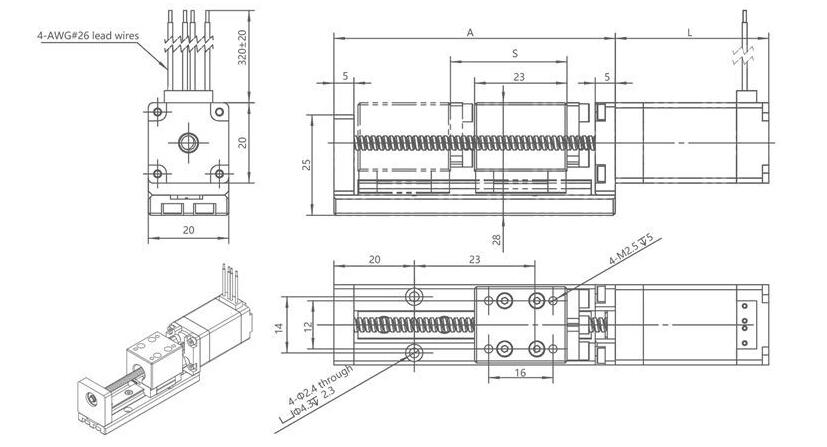
Stroke S (mm) | 30 | 60 | 90 | Size can |
Dimension A (mm) | 70 | 100 | 130 |
Customized NEMA8 Linear with origin switch outline drawing:
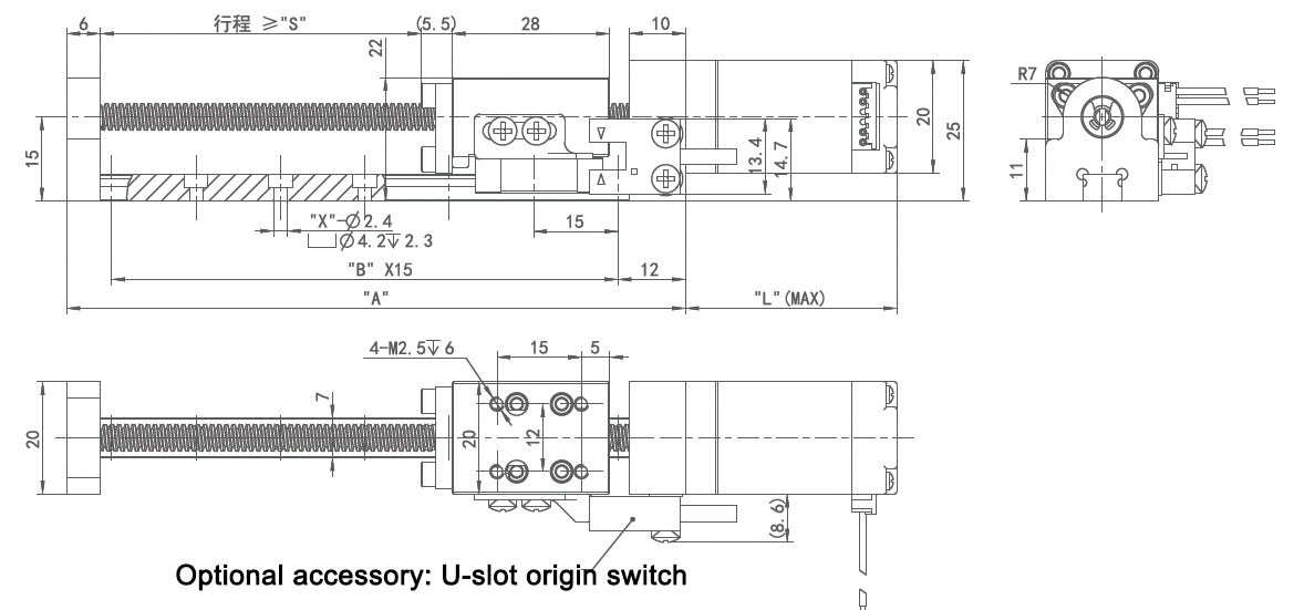
More Information on detail, please feel free to contact me

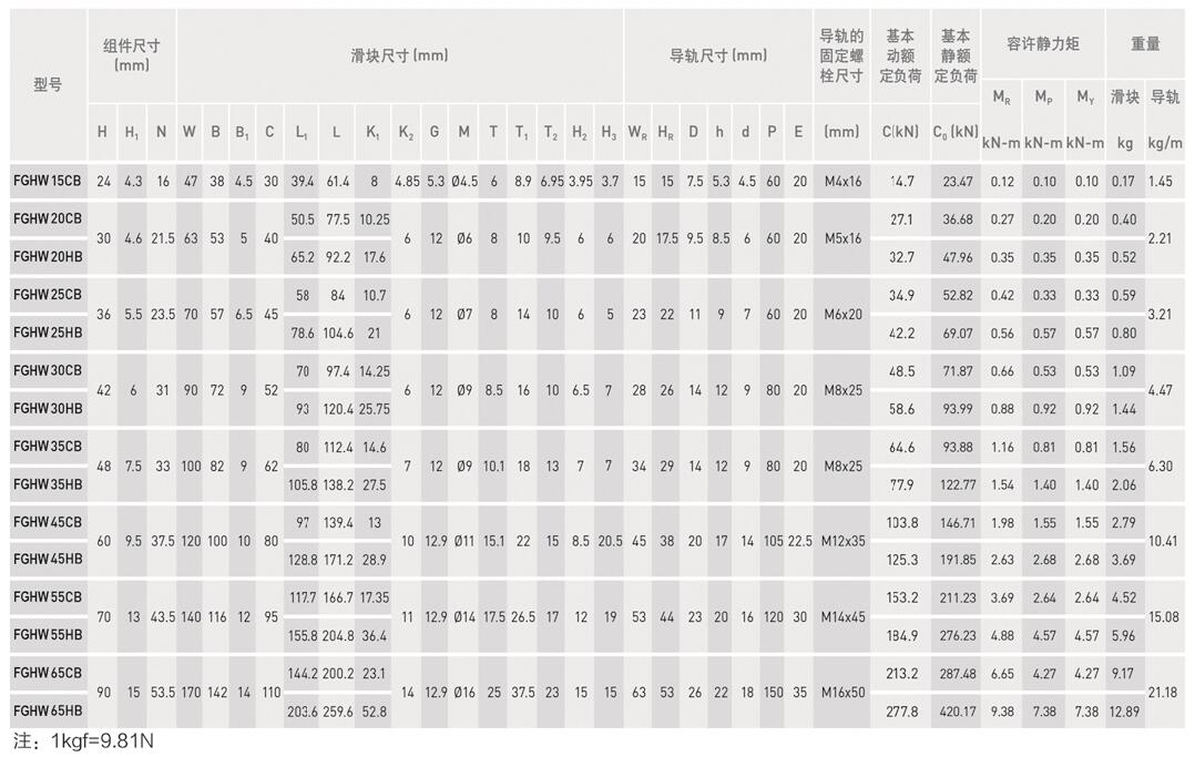
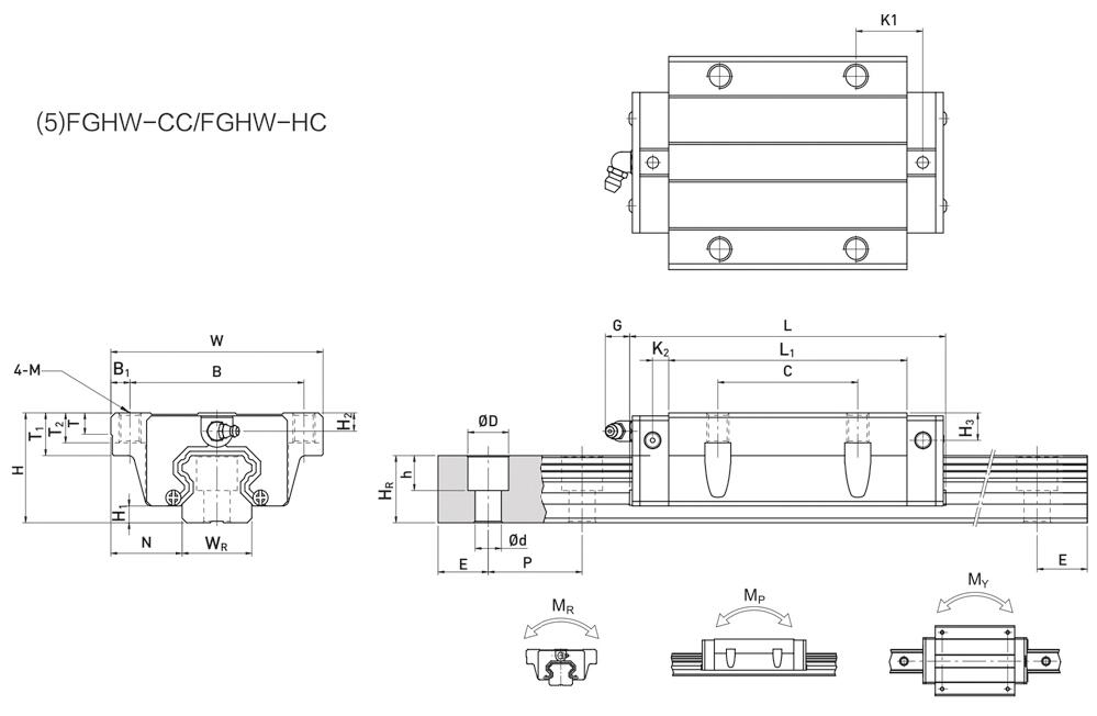
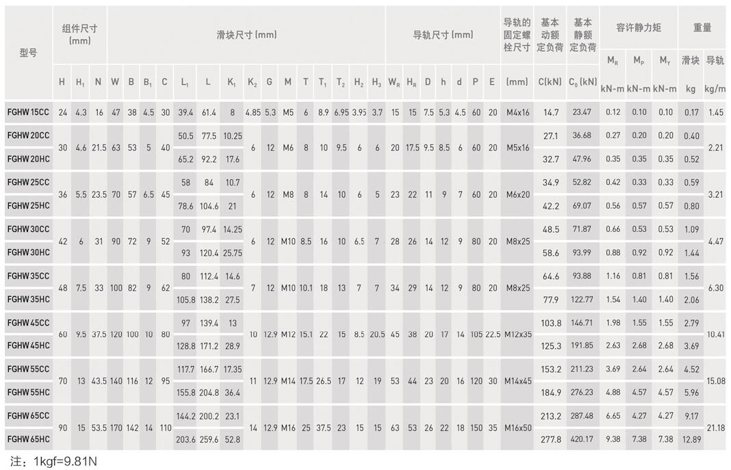
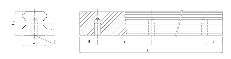
SPHERICAL GUIDE, Linear Guideway.
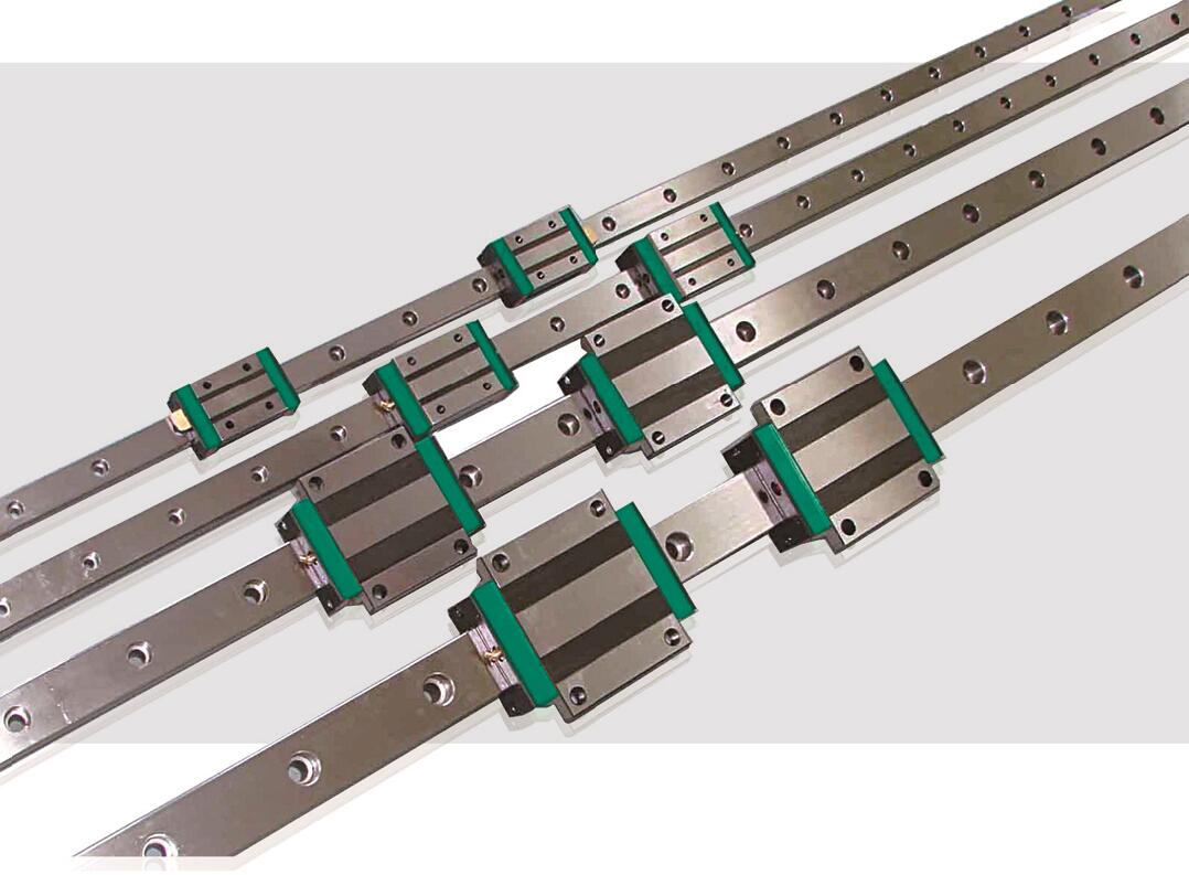
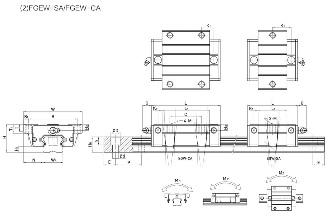
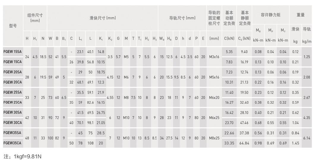
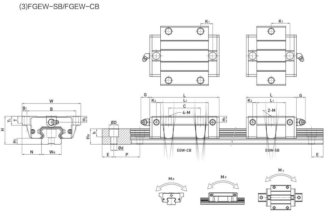
Linear Guideway, Heavy Load Ball Linear Guide, low assembly ball linear guide, and miniature ball linear guide:
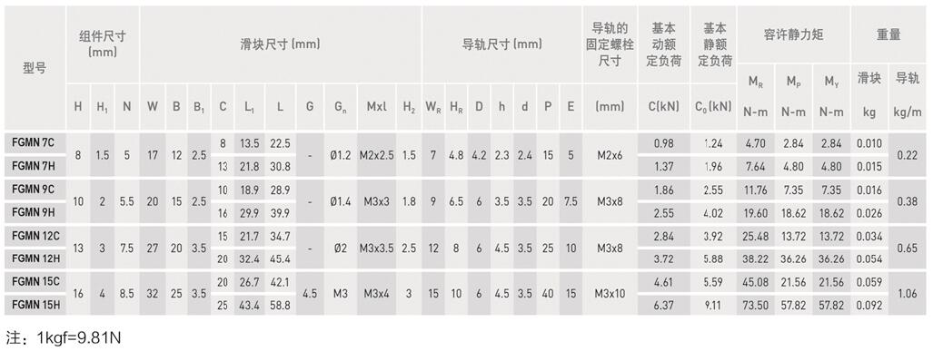
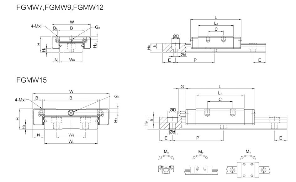
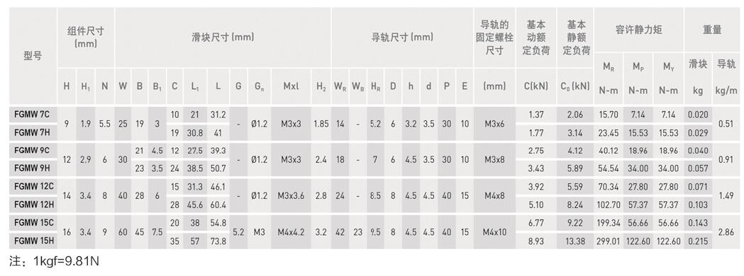
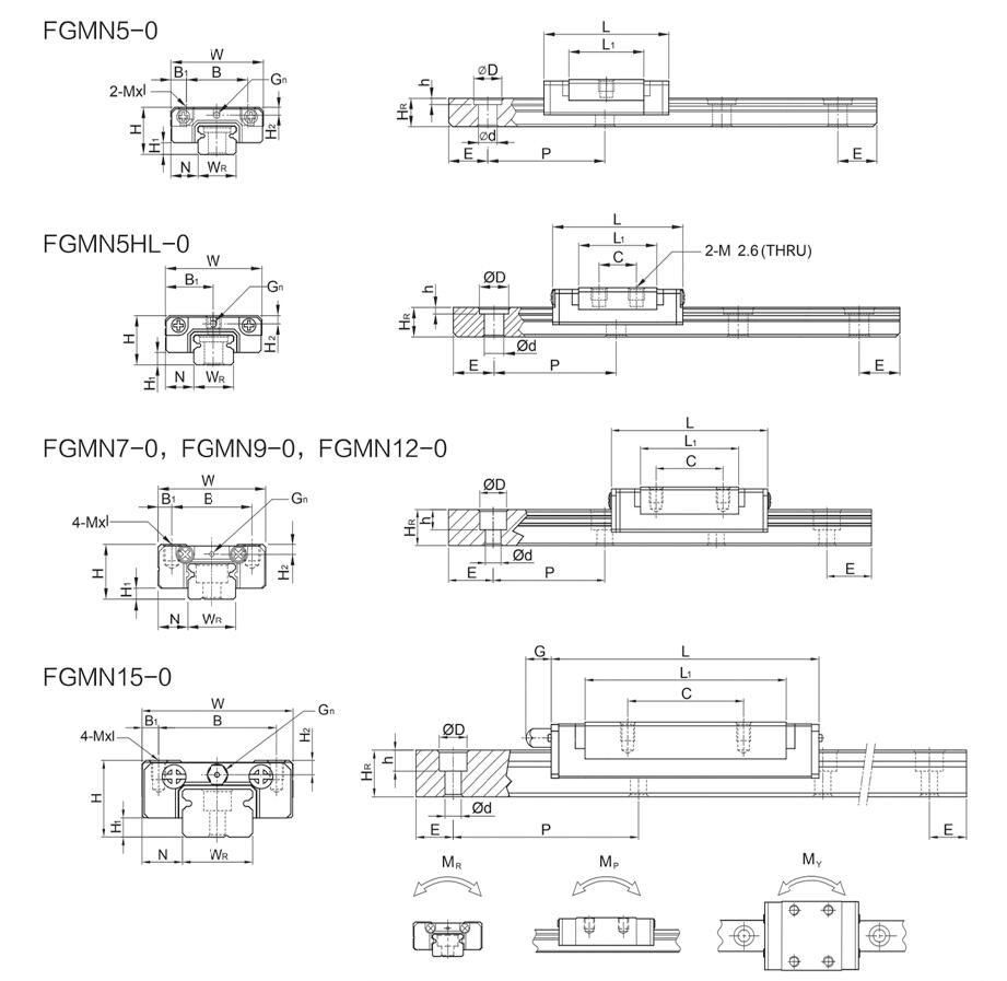
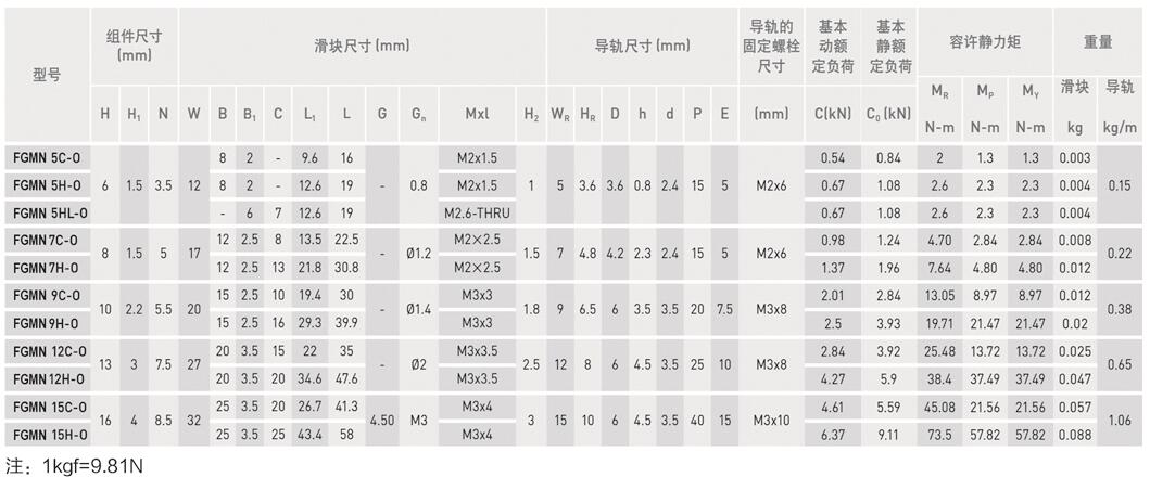
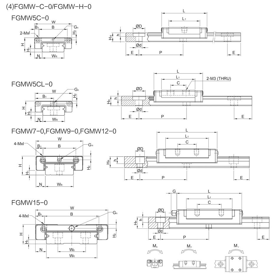
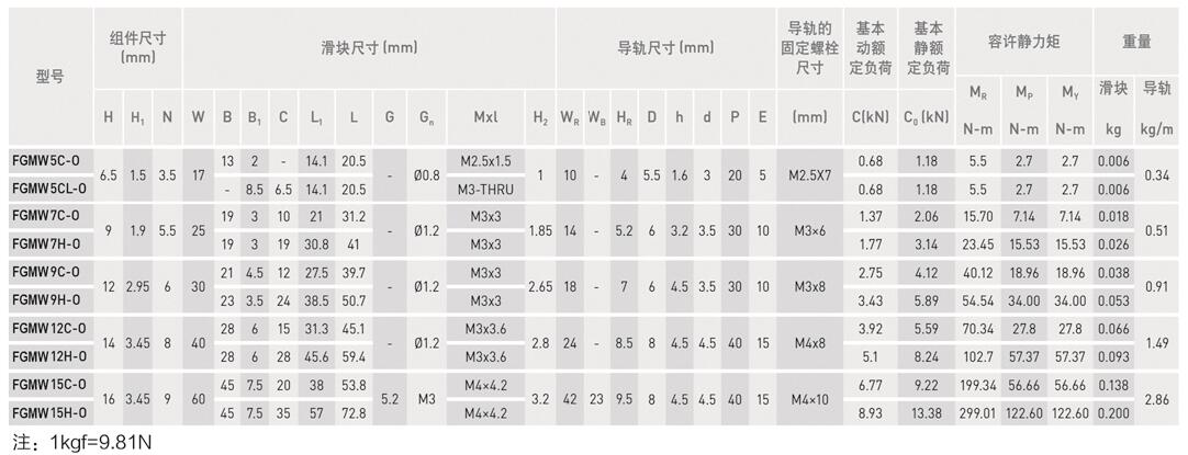
FGM series miniature ball linear guide: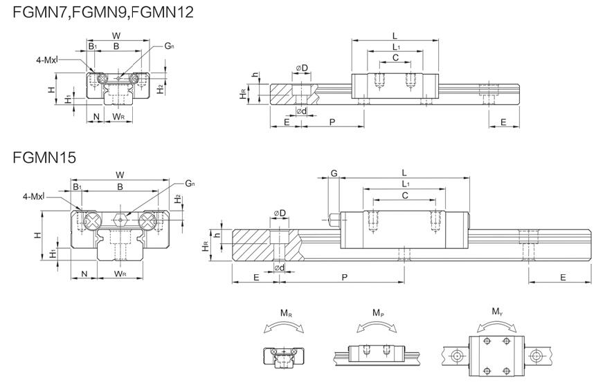
PGEH series low assembly ball linear guide: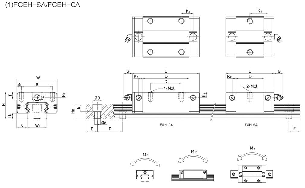
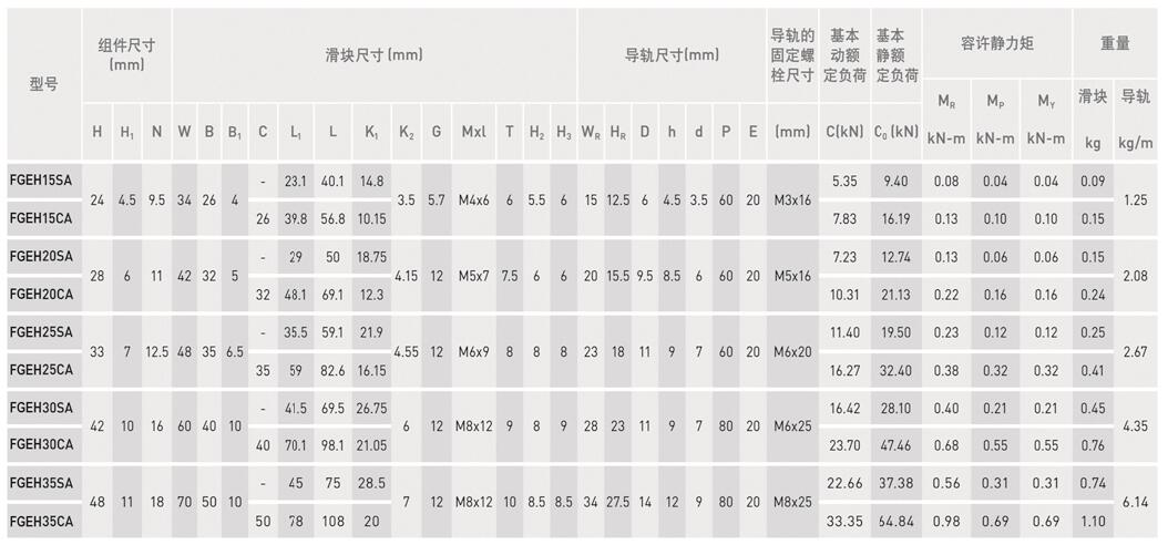
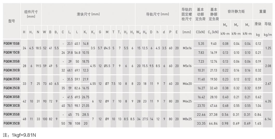
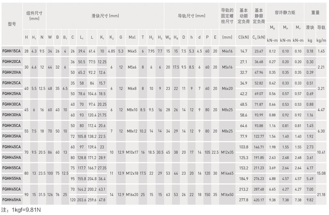
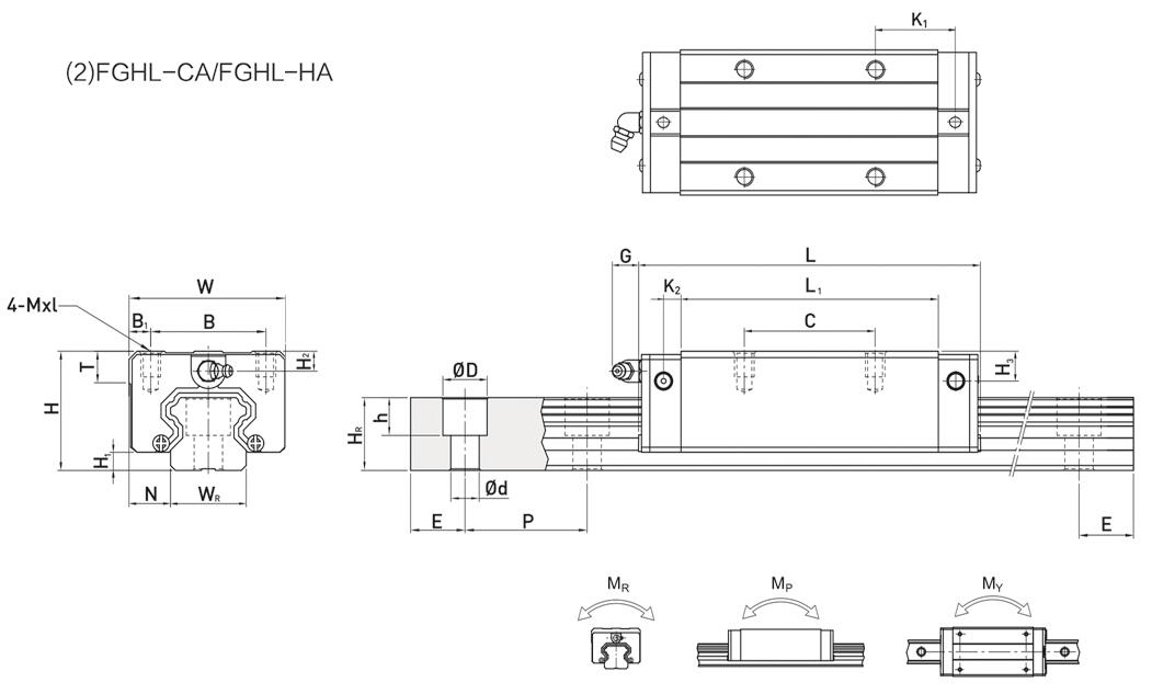
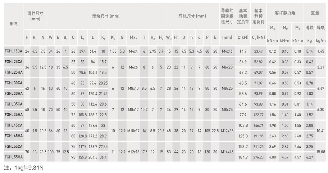
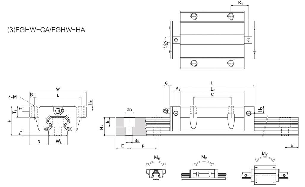
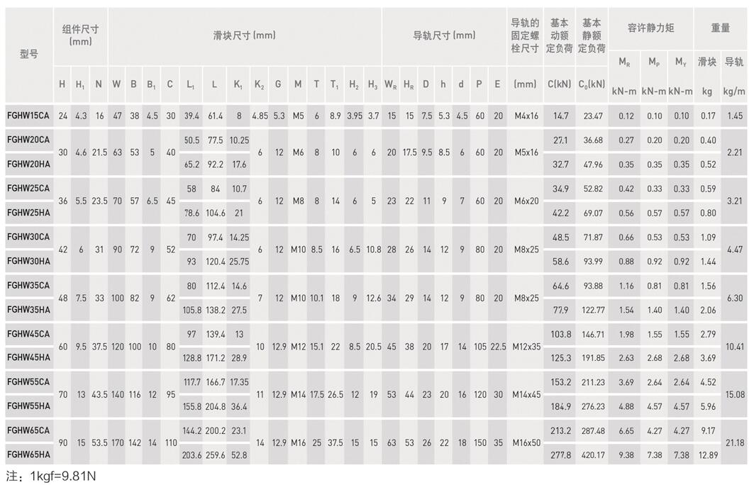
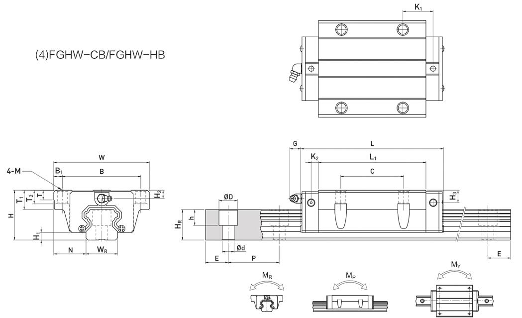
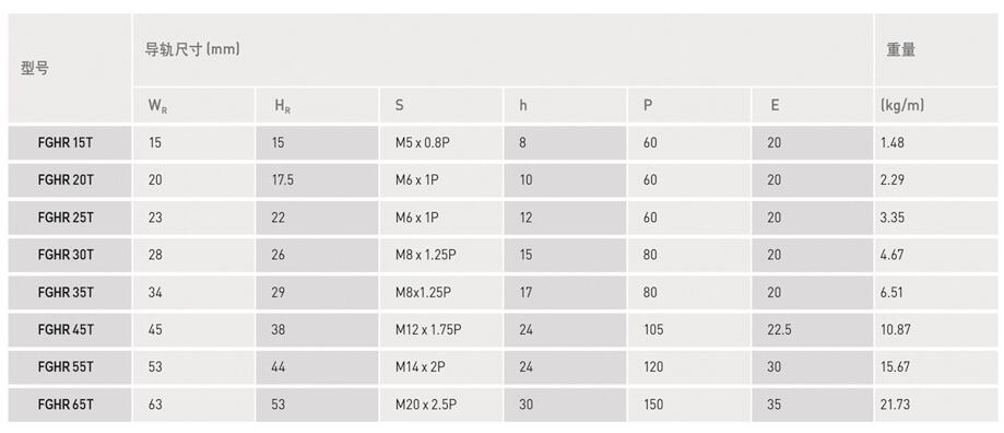
FGH series Heavy Load ball linear guide: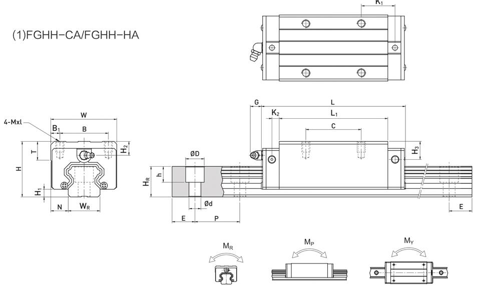
More Information on detail, please feel free to contact me

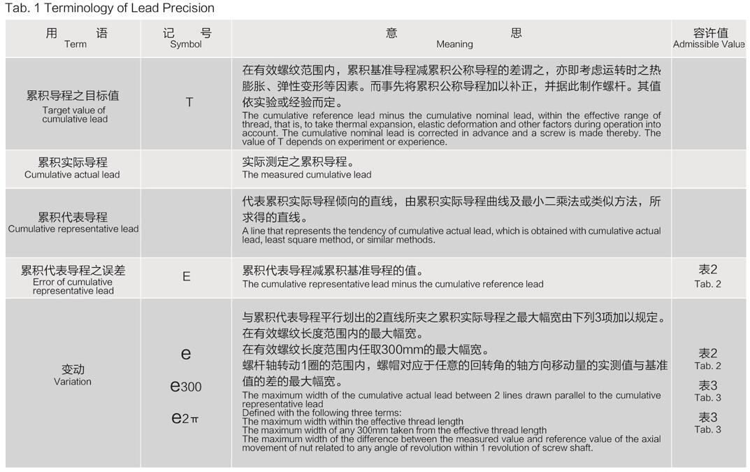
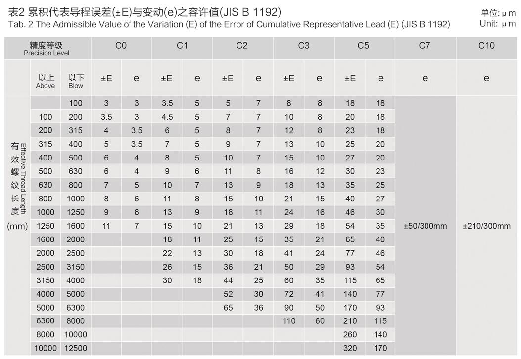
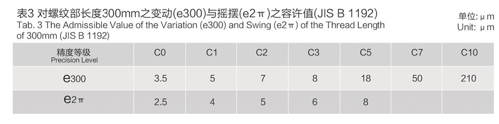
The lead precision of AdamPower precision ball screws (C3-C5) is based on JlS specifications
and specified with four features (Ee. e300 and e2r). The definition and admissible value of
each feature are shown in Fig. 1 and Tabs. 1-3. Generaly speaking, thecumulative lead errors
of bal screws C7 and C10 are used. the admissible value of the error of any 300mm taken
from the efectiveength of screw and e300 in Tab. 3. which are 0.05mm and 0.21mm respectively.
are used to definite the precision.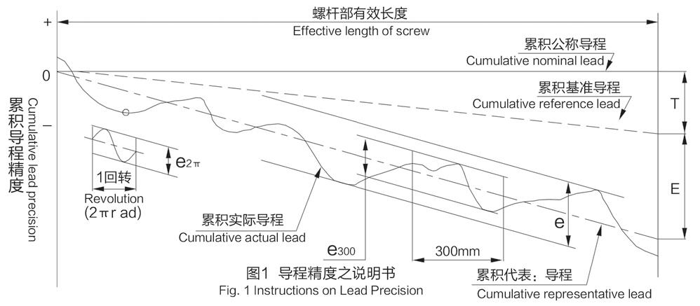
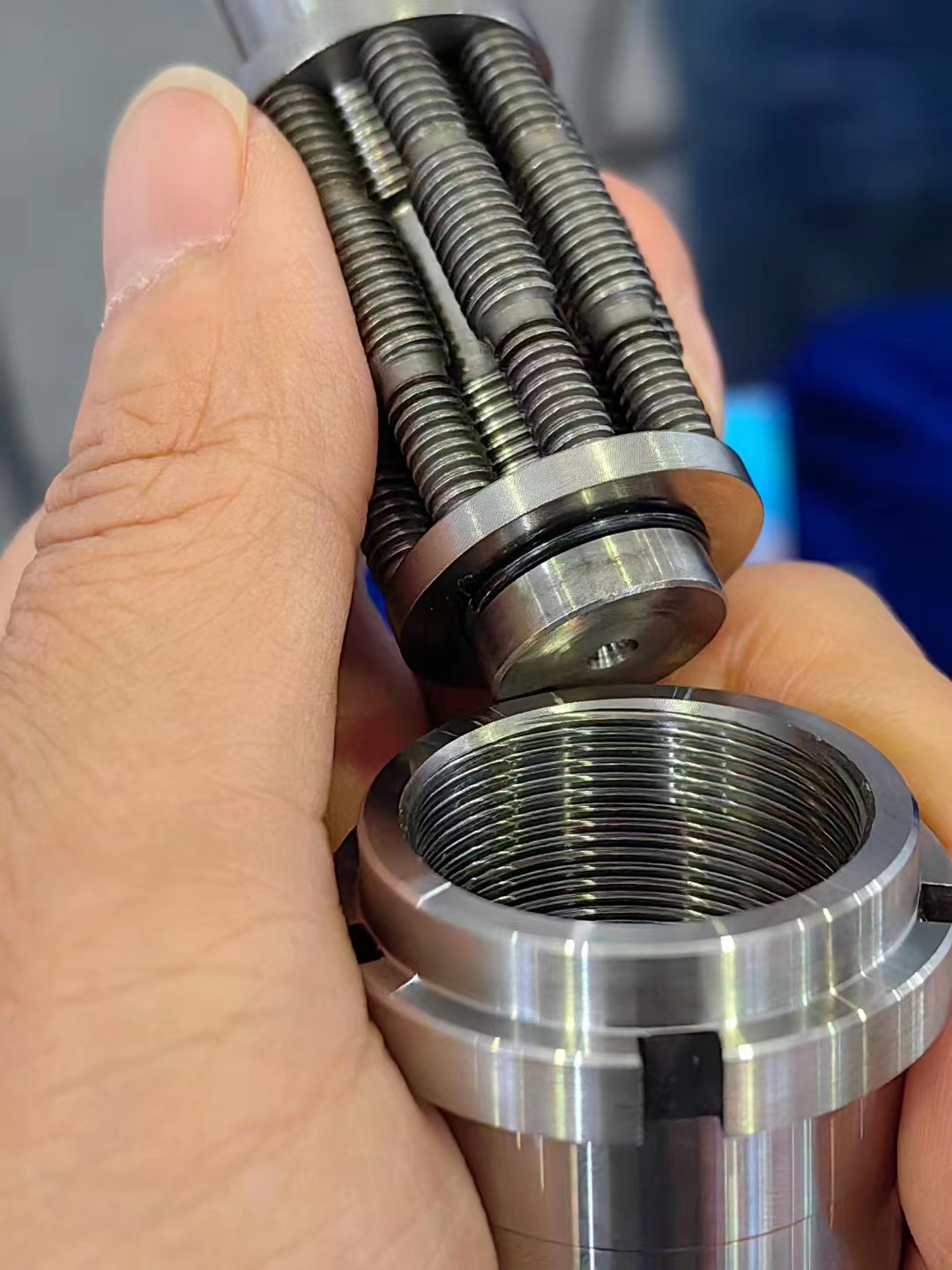
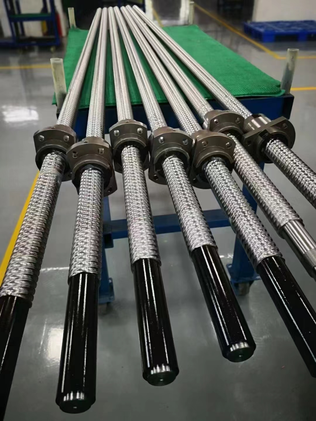
Ball Screw can be customized for special application requirement, ball thread length, full length of the screw, thread
direction: Right-handed or left-handed, and different nut structure(I, U, A, Y, S, K), and so on.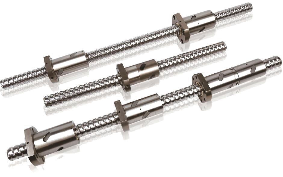
Numbering Rule of the Ball Screw: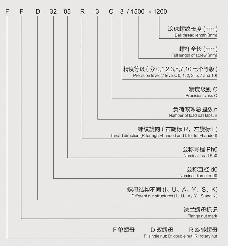
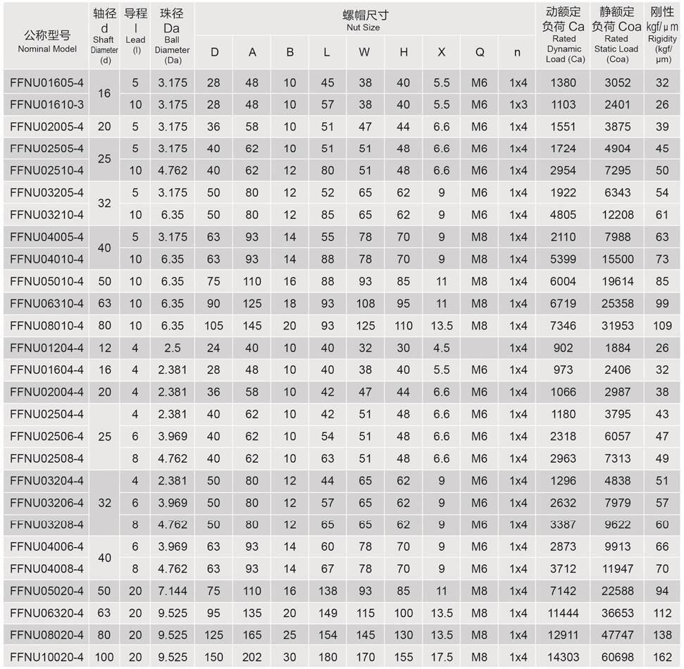
FFNU series Ball Screw:
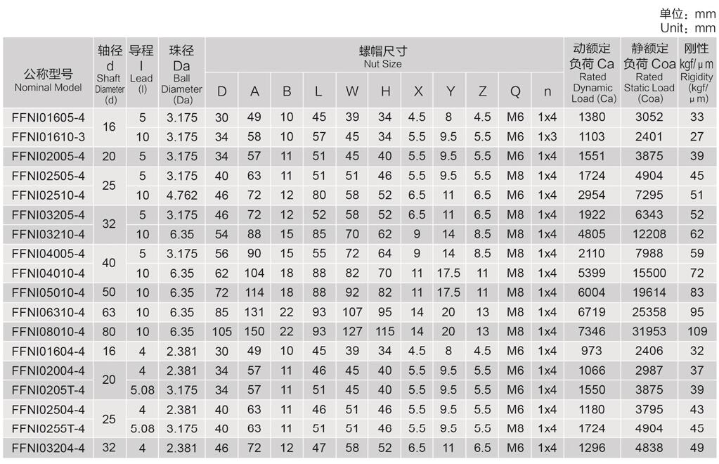
FFNI series Ball Screw: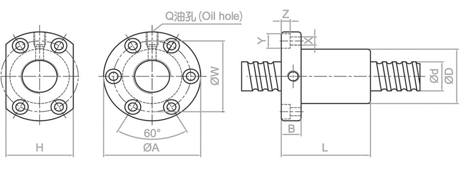
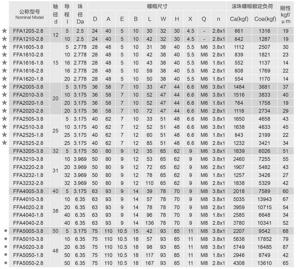
FFA series Ball Screw: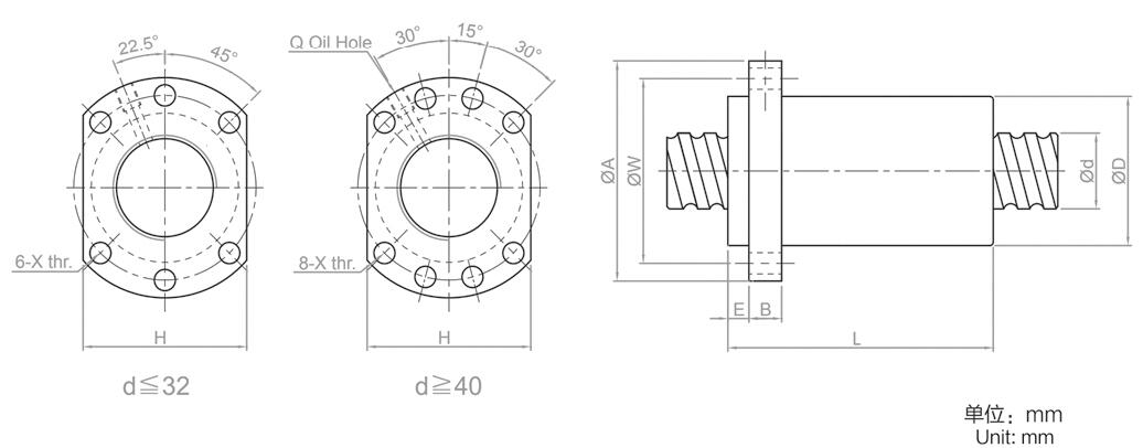
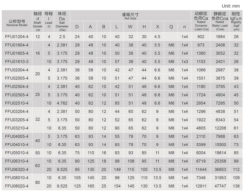
FFU series Ball Screw: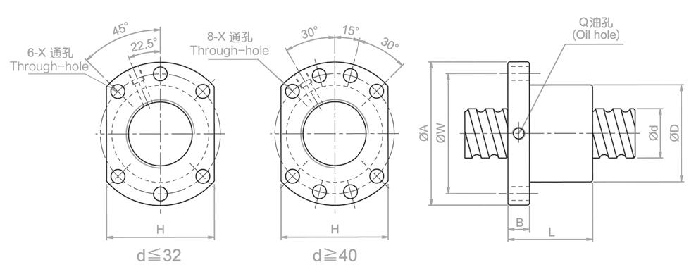
FFK series Ball Screw:
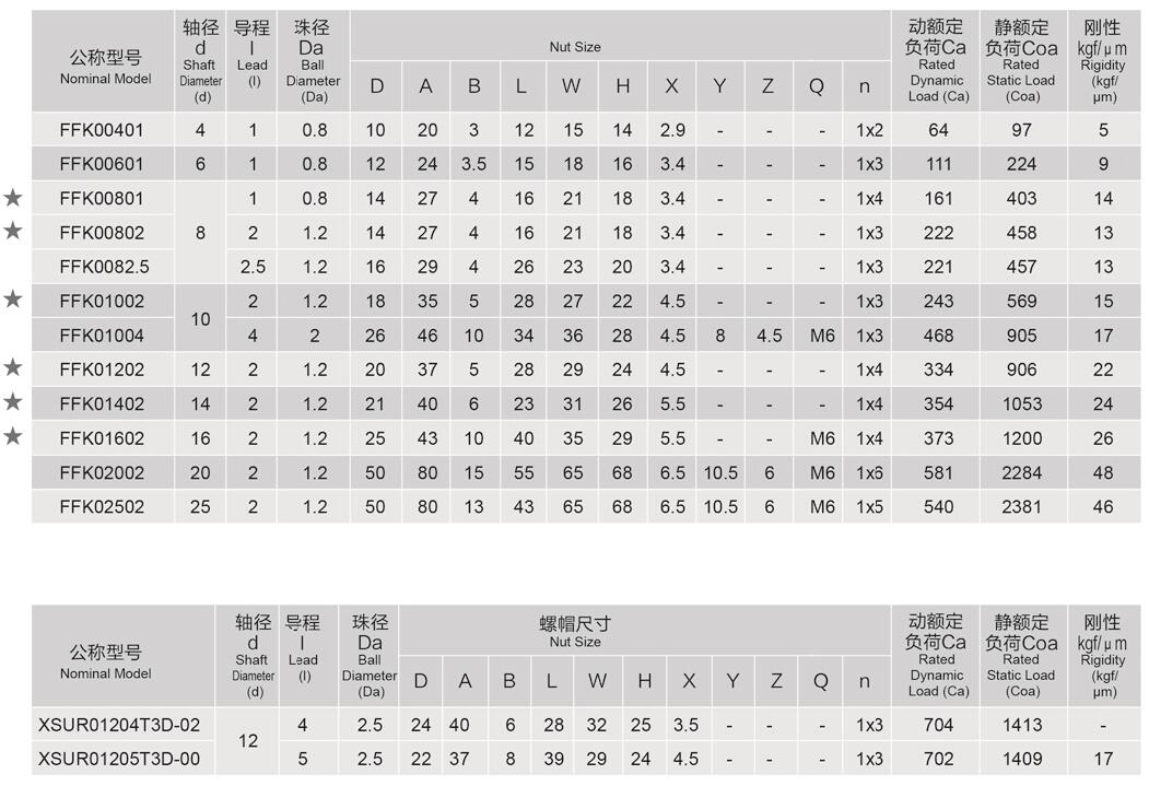
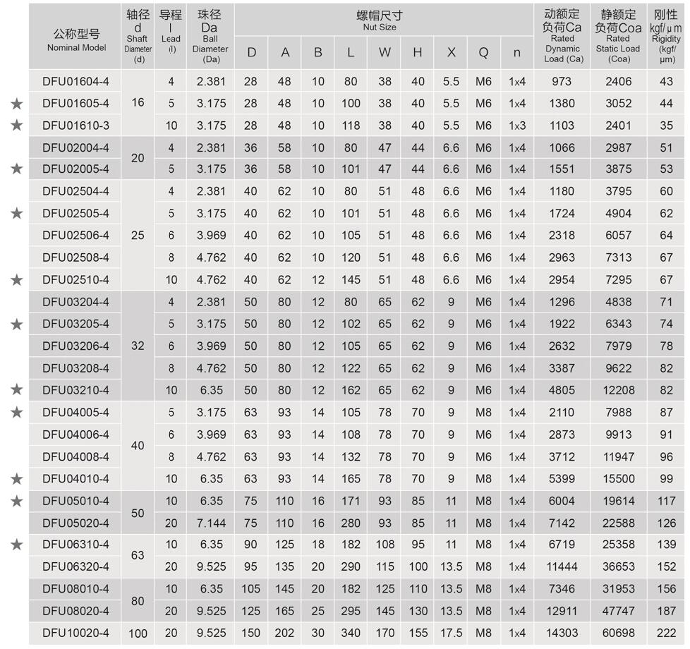
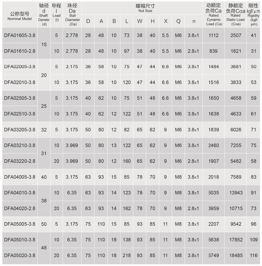
DFU series Ball Screw: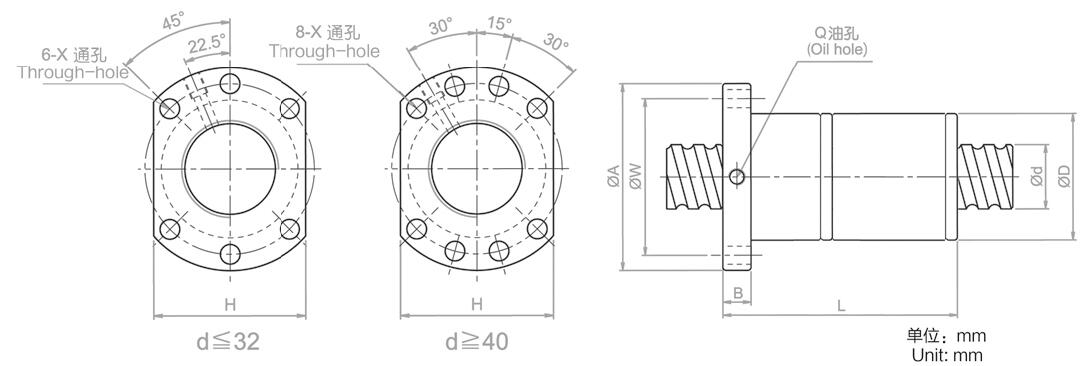
DFA series Ball Screw: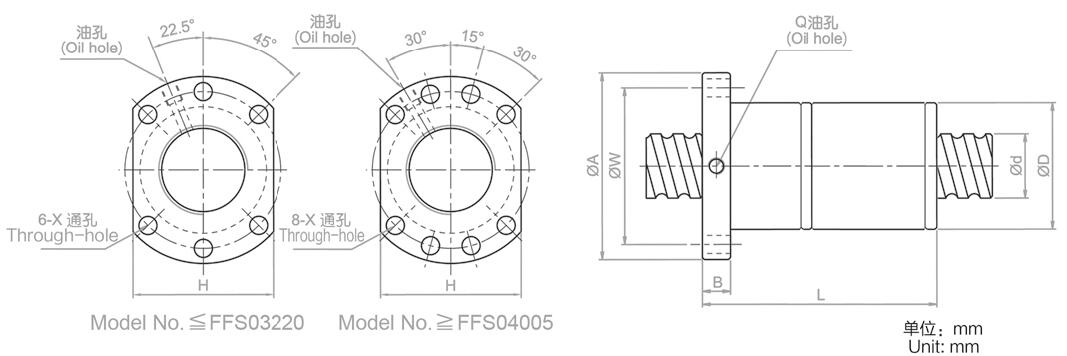
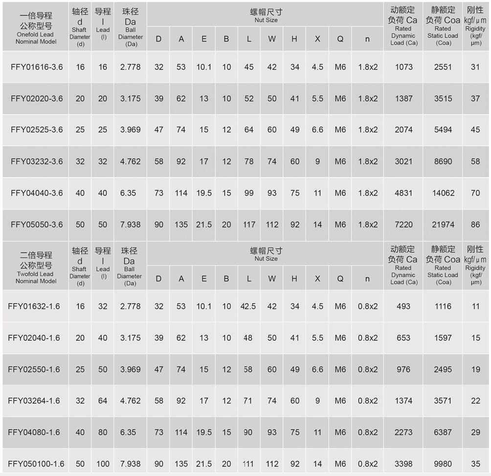
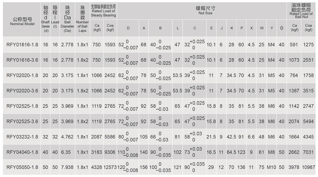
FFY series Ball Screw: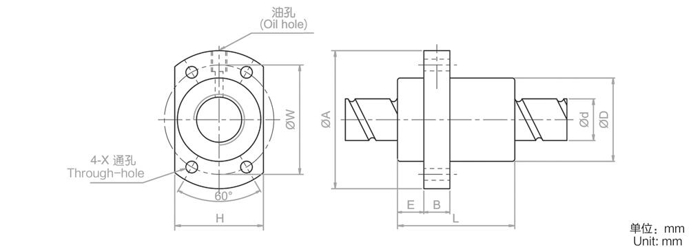
RFY series Ball Screw: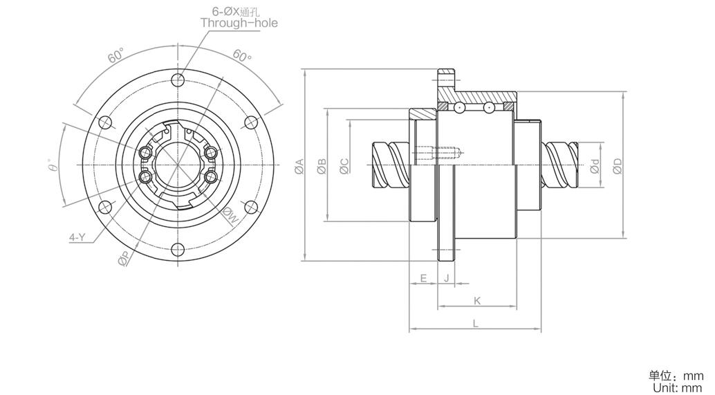
More Information on detail, please feel free to contact me

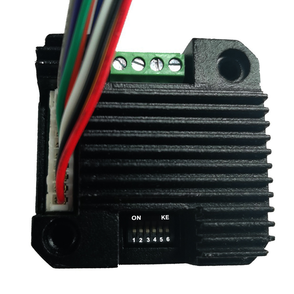
Pulse & direction stepper motor driver, support to Spontaneous pulses.
Spontaneous pulses Stepper Motor Driver
 | ADH42 | |||
minimum value | Typical value | Maximum value | Unit | |
Supply Voltage (DC) | 12 | 24 | 40 | VDC |
Control Signal | 7 | 10 | 16 | mA |
Step pulse frequency | 0 | - | 200 | KHz |
insulation resistance | 50 |
|
| MΩ |
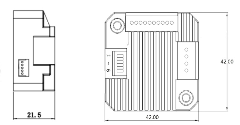
● Miniature size 42mmx42mm x21.5mm
● Pulse & direction stepper driver also support the standard RS232 serial command, and built-in 32bit digital chip.
● Using new control algorithms such for vibration suppression and low heat generation
● DC input voltage 12~40VDC, recommended working voltage 24VDC.
● Continuous output current 1.4A max, max peak current 2.1A.
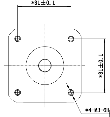
● Integrated design, mounted with 42/39mm stepper motor.
● Low vibration, low noise, stable operation, low motor heating.
● Any micro-step can be set .
● Protection functions such as overvoltage, undervoltage and overcurrent.
● Built-in automatic matching function of motor parameter.
● ADM42H stepper driver can be assembled for NEMA17 Integrated Stepper Motors
| Pin No. | Name | Description |
| 1 | PU | Pulse Control Signal Input: 5V ~ 24V, Rising Edge effective, Make sure pulse signal effective, pulse width ≥ 2μs Add the resistance for power supply. |
| 2 | PU- | |
| 3 | DR | Direction Signal: high/low level signal: 5V ~ 24V, direction signal should be at least 5 μs earlier than pulse signal, High/Low level. |
| 4 | DR- | |
| 5 | EN | Enable Signal:enable/disable. If ENA connect 5V & ENA- connect low level(or Internal optocoupler on), stepper controller will turn off the current, motor in free state, no feedback even send pulses. |
| 6 | EN- | |
| 7 | AM | Alarm signal output: When overvoltage, undervoltage, phase loss, or position deviation alarms occur, the alarm signal output is effective; Maximum driving current 50mA |
| 8 | AM- | |
| 9 | GND | Supply Voltage Ground: GND/0V |
| 10 | DC | Supply voltage: 12-40VDC, Recommend DC24V |
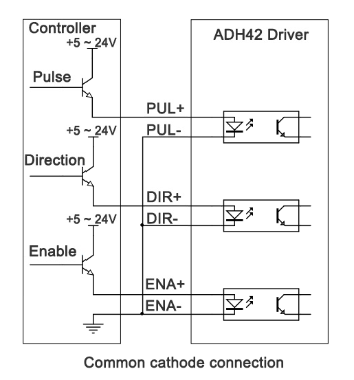
Wire support common anode connection and common cathode connection, controlled by PLC or Pulse Generators.
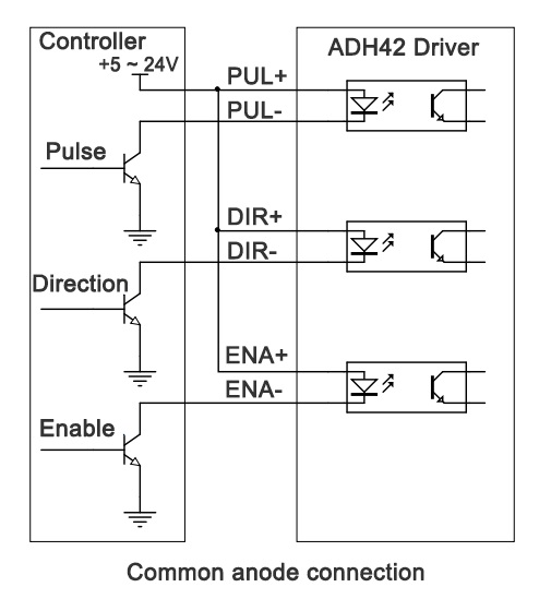
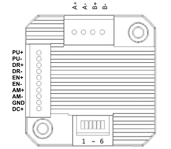
DIP Switch SW1 SW2 SW3 SW4 SW5 SW6 ↑
1. Set working current by SW1:
SW1 | Peak(A) | RMS(A) |
off | 1.4 | 1.0 |
on | 2.1 | 1.5 |
2. Set Working Mode by SW2:
SW2 | Working Mode |
off | Pulse & Direction |
on | Spontaneous pulses |
2.1. Pulse & Direction working mode:
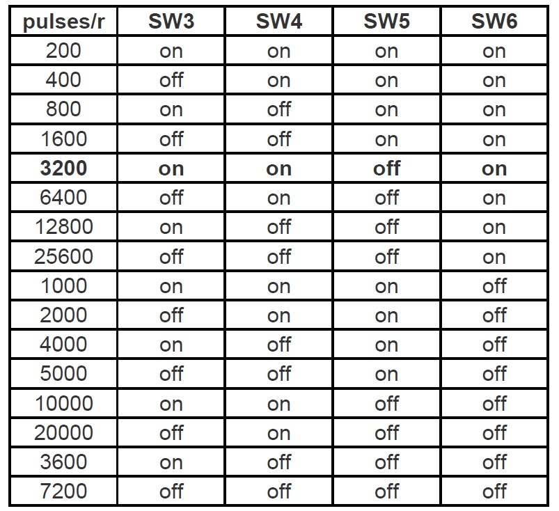
Set Micro-step by SW3,SW4,SW5 SW6:
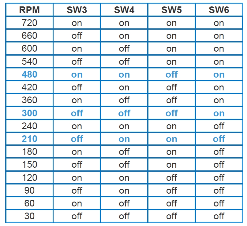
2.1. Spontaneous pulses working mode:
In this working mode, the PU PU- connect to the power supply 5~24VDC and GND,
make sure the stepper motors rotates instantly when power on, please check below wiring diagram: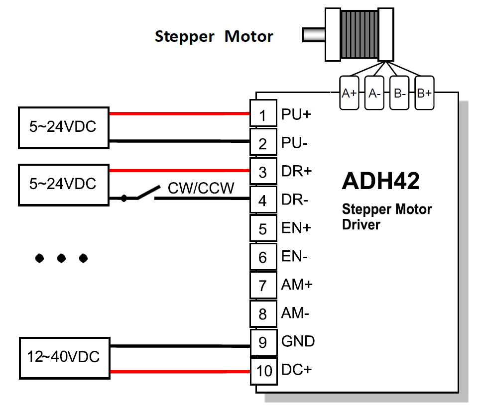
Set Working Speed by SW3,SW4,SW5 SW6:
More Information on detail, please feel free to contact me

NEMA8 Stepper Lead Screw Linear Actuators
The NEMA 6 is our smallest hybrid linear actuators.
This compact unit can be integrated into various
Applications to provide precise linear positioning while
occupying less than 1 in2 of mounting footprint and
providing up to 44.5N of continuous thrust.
The Working Type for the Different Application Demand:
E: External Linear
N: Non-captive
C: Captive
K: Kaptive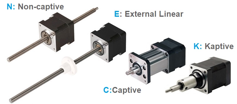
Motor Characteristics:
| Motor Code | Voltage (V) | Current (A) | Resistance (Ω) | Inductance (mH) | Weight (g) | Lead Wire No | Length (mm) |
| 8-2105 | 2.5 | 0.5 | 5.1 | 1.5 | 51 | 4 | 27.2 |
| 8-2205 | 4.4 | 0.5 | 8.8 | 2.7 | 74 | 4 | 38.1 |
| Lead Code | Screw Dia. (inch) | Screw Dia. (mm) | Lead (inch) | Lead (mm) | Travel Per Step @ 1.8 deg (mm) |
| AF | 0.138 | 3.5 | 0.012 | 0.3048 | 0.0015 |
| AA | 0.138 | 3.5 | 0.024 | 0.6096 | 0.003 |
| B | 0.138 | 3.5 | 0.048 | 1.2192 | 0.0061 |
| G | 0.138 | 3.5 | 0.079 | 2 | 0.01 |
| M | 0.138 | 3.5 | 0.158 | 4 | 0.02 |
| T | 0.138 | 3.5 | 0.315 | 8 | 0.04 |
NEMA 8 Stepper Lead Screw Linear Actuators (External Type):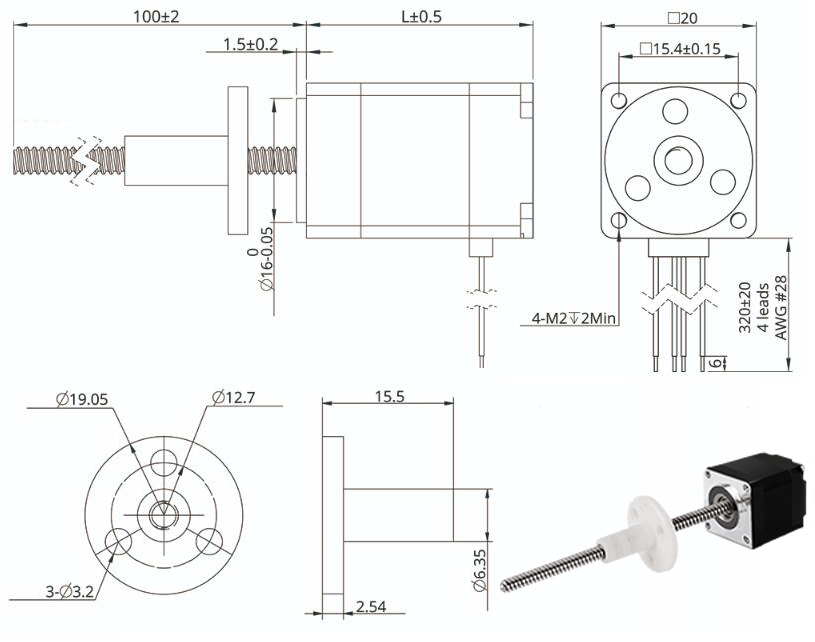
NEMA 8 Stepper Lead Screw Linear Actuators (Non-Captive Type):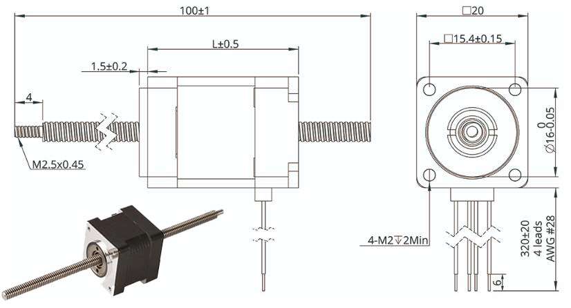
NEMA 8 Stepper Lead Screw Linear Actuators (Kaptive Type):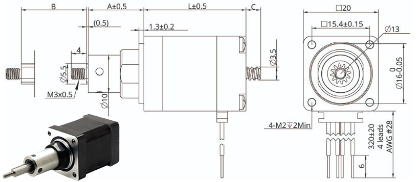
Stroke Specification of Kaptive Actuactor:
| A(mm) | Stroke B (mm) | C(mm) | |
| L=27.2 | L=38.1 | ||
| 11.2 | 9 | 1 | 0 |
| 14.9 | 12.7 | 5 | 0 |
| 21.1 | 19.05 | 11 | 0 |
| 27.6 | 25.4 | 17 | 6 |
| 34 | 31.8 | 24 | 13 |
| 40.3 | 38.1 | 30 | 19 |
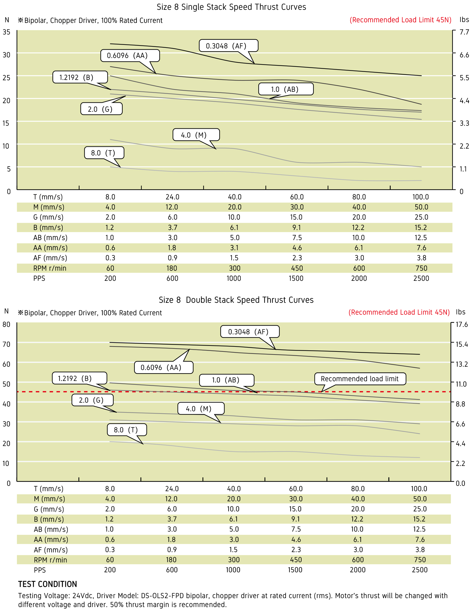
Speed Thrust Curves:
Options for screw end machining:
Catalog for download
More Information on detail, please feel free to contact me

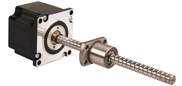
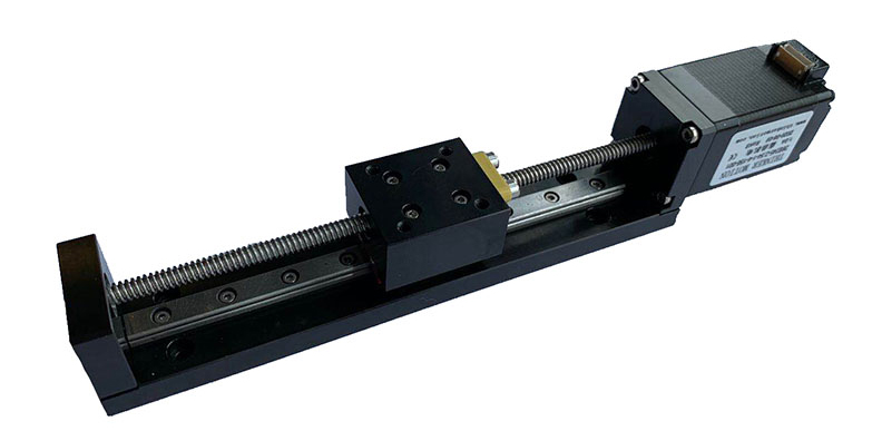
NEMA23 Stepper Ball Screw Linear Actuators
These actuators are external types have 5 different sizes, from 20mm to 57mm. From 0.005mm/
step to 0.1mm/step, variety of resolution for options available. Maximum thrust can reach 1600N.
Encoder option is available for whole Series
| Motor size | NEMA8 | NEMA11 | NEMA14 | NEMA17 | NEMA23 | ||||
| Dia. Lead | Φ4 | Φ5 | Φ6 | Φ6 | Φ8 | Φ6 | Φ8 | Φ10 | Φ12 |
| 1.0 mm | * | * | * | * | * | * | |||
| 2.0 mm | * | * | * | * | * | * | * | * | |
| 2.5 mm | * | * | |||||||
| 4.0 mm | * | * | |||||||
| 5.0 mm | * | * | * | ||||||
| 6.0 mm | * | * | * | ||||||
| 8.0 mm | * | * | |||||||
| 10.0 mm | * | * | * | * | * | * | * | ||
| 12.0 mm | * | * | |||||||
| 15.0 mm | * | ||||||||
| 20.0 mm | * | ||||||||
NEMA23 Stepper Ball Screw Linear Actuators
Motor Characteristics:
| Motor Code | Voltage (V) | Current (A) | Resistance (Ω) | Inductance (mH) | Lead Wire No | Length (mm) |
| 23E2110 | 6.4 | 1.0 | 6.4 | 16.4 | 4 | 45 |
| 23E2120 | 3.5 | 2.0 | 1.75 | 4.1 | 4 | 45 |
| 23E2130 | 2.4 | 3.0 | 0.8 | 1.7 | 4 | 45 |
| 23E2210 | 11.5 | 1.0 | 11.5 | 32 | 4 | 65 |
| 23E2225 | 5.0 | 2.5 | 2.0 | 5.2 | 4 | 65 |
| 23E2240 | 2.8 | 4.0 | 0.7 | 2.0 | 4 | 65 |
| Ball screw type | 1002 | 1004 | 1005 | 1010 | 1015 | 1020 | 1202 | 1210 |
|---|---|---|---|---|---|---|---|---|
| Ball Size | Ф1.5875 | Ф2.0 | Ф2.0 | Ф2.0 | Ф2.0 | Ф1.5875 | Ф1.5875 | Ф2.381 |
| Number of thread | 1 | 1 | 1 | 2 | 2 | 4 | 1 | 2 |
| Thread direction | Right | |||||||
| Shaft root dia. | Ф8.6 | Ф8.2 | Ф8.2 | Ф8.4 | Ф8.4 | Ф8.7 | Ф10.6 | Ф10.2 |
| Number of circuit | 3.7×1 | 2.7×1 | 2.7×1 | 1.6×2 | 1.6×2 | 0.7×4 | 3.7×1 | 1.7 x 2 |
| Shaft, nut material | SCM415H | |||||||
| Surface hardness | HRC58~62 | |||||||
| Anti-rust treatment | Anti-rust oil | |||||||
| Grade | C7 | |||||||
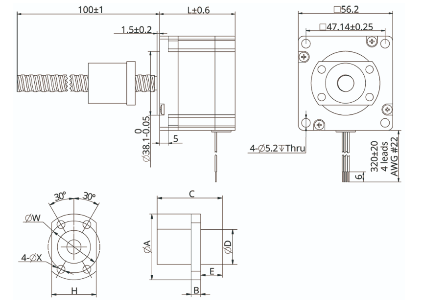
| Nut size | A | B | C | D | H | W | X | E | Position accuracy | Total run out | Axial play | Dynamic load[N] | Static load[N] |
|---|---|---|---|---|---|---|---|---|---|---|---|---|---|
| BS1002 | 40 | 5 | 24 | 23 | 25 | 32 | 4.5 | ±0.05 | 0.12 | ≤0.03 | 2700 | 5300 | |
| BS1004 | 41 | 5 | 28 | 24 | 26 | 33 | 4.5 | ±0.05 | 0.12 | ≤0.03 | 3000 | 5200 | |
| BS1005 | 40 | 5 | 26 | 23 | 25 | 32 | 4.5 | ±0.05 | 0.12 | ≤0.03 | 3000 | 5200 | |
| BS1010 | 40 | 5 | 24 | 23 | 25 | 32 | 4.5 | 6 | ±0.05 | 0.12 | ≤0.03 | 3300 | 5900 |
| BS1015 | 40 | 5 | 33 | 23 | 25 | 32 | 4.5 | 6 | ±0.05 | 0.12 | ≤0.03 | 3300 | 6400 |
| BS1020 | 37 | 5 | 23 | 20 | 22 | 29 | 4.5 | 5 | ±0.05 | 0.12 | ≤0.03 | 2100 | 4000 |
| BS1202 | 42 | 5 | 24 | 25 | 27 | 34 | 4.5 | ±0.05 | 0.12 | ≤0.03 | 3000 | 6400 | |
| BS1210 | 41 | 5 | 30 | 24 | 26 | 33 | 4.5 | 9.5 | ±0.05 | 0.12 | ≤0.03 | 5100 | 9800 |
* The unit of Position accuracy, Total run out and Axial play is [mm].
NEMA 23 Ball Screw Liner Stepper Motor Performance Curves: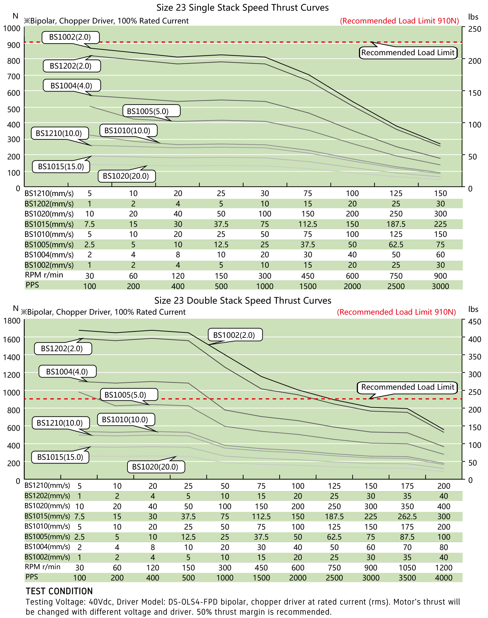
Options for screw end machining:
Catalog for download
More Information on detail, please feel free to contact me
Size:
NEMA8, NEMA11, NEMA14, NEMA17, NEMA23, NEMA23, NEMA34
20mm, 28mm, 35mm, 42mm, 57mm, 60mm, 86mm
Stepper
0.001524mm~0.16mm
Performance
Maximum thrust up to 240kg, low temperature rise, low vibration, low noise,
long life (up to 5 million cycles), and high positioning accuracy (up to ±0.005 mm)
Application
Medical diagnostic equipment, life science instruments, robots, optical equipment,
analytical instruments, semiconductor equipment, communication equipment, automation equipment
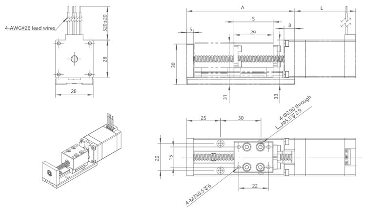
NEMA14 Lead Screw Linear Actuators
Linear Module, Linear Slider
| Motor Type | Bipolar stepper |
| Step Angle | 1.8° |
| Voltage (V) | 1.4 / 2.9 |
| Current (A) | 1.5 |
| Resistance (Ohms) | 0.95 / 1.9 |
| Inductance (mH) | 1.4 / 3.2 |
| Lead Wires | 4 |
| Motor Length (mm) | 34 / 47 |
| Stroke (mm) | 30 / 60 / 90 |
| Ambient Temperature | -20℃ ~ 50℃ |
| Temperature Rise | 80K Max. |
| Dielectric Strength | 1mA Max. @ 500V, 1KHz, 1Sec. |
| Insulation Resistance | 100MΩ Min. @500Vdc |
Motor Characteristics:
Motor Size | Voltage/ Phase (V) | Current/ Phase (A) | Resistance/ Phase (Ω) | Inductance/ Phase (mH) | Number of Lead Wires | Rotor Inertia (g.cm2) | Motor Weight (g) | Motor Length L (mm) |
35 | 1.4 | 1.5 | 0.95 | 1.4 | 4 | 20 | 190 | 34 |
35 | 2.9 | 1.5 | 1.9 | 3.2 | 4 | 30 | 230 | 47 |
Available Lead Screw and Travel per Step:
Diameter (mm) | Lead (mm) | Step (mm) | Power off self-locking force (N) |
6.35 | 1.27 | 0.00635 | 150 |
6.35 | 3.175 | 0.015875 | 40 |
6.35 | 6.35 | 0.03175 | 15 |
6.35 | 12.7 | 0.0635 | 3 |
6.35 | 25.4 | 0.127 | 0 |
NEMA14 Linear Actuator outline drawing:
Stroke S (mm) | 30 | 60 | 90 |
Dimension A (mm) | 90 | 120 | 150 |
More Information on detail, please feel free to contact me
Size:
NEMA8, NEMA11, NEMA14, NEMA17, NEMA23, NEMA23, NEMA34
20mm, 28mm, 35mm, 42mm, 57mm, 60mm, 86mm
Stepper
0.001524mm~0.16mm
Performance
Maximum thrust up to 240kg, low temperature rise, low vibration, low noise,
long life (up to 5 million cycles), and high positioning accuracy (up to ±0.005 mm)
Application
Medical diagnostic equipment, life science instruments, robots, optical equipment,
analytical instruments, semiconductor equipment, communication equipment, automation equipment
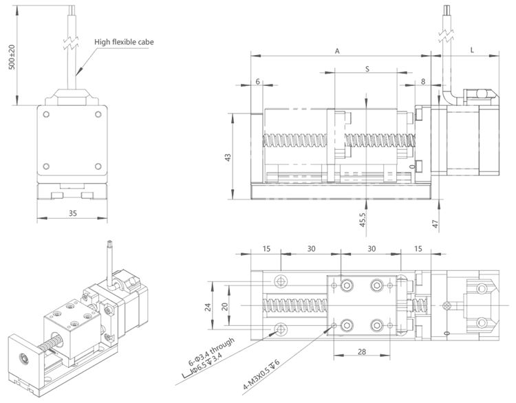
NEMA11 Lead Screw Linear Actuators
Linear Module, Linear Slider
| Motor Type | Bipolar stepper |
| Step Angle | 1.8° |
| Voltage (V) | 2.1 / 3.7 |
| Current (A) | 1 |
| Resistance (Ohms) | 2.1 / 3.7 |
| Inductance (mH) | 1.5 / 2.3 |
| Lead Wires | 4 |
| Motor Length (mm) | 34 / 45 |
| Stroke (mm) | 30 / 60 / 90 |
| Ambient Temperature | -20℃ ~ 50℃ |
| Temperature Rise | 80K Max. |
| Dielectric Strength | 1mA Max. @ 500V, 1KHz, 1Sec. |
| Insulation Resistance | 100MΩ Min. @500Vdc |
Motor Characteristics:
Motor Size | Voltage/ Phase (V) | Current/ Phase (A) | Resistance/ Phase (Ω) | Inductance/ Phase (mH) | Number of Lead Wires | Rotor Inertia (g.cm2) | Motor Weight (g) | Motor Length L (mm) |
28 | 2.1 | 1 | 2.1 | 1.5 | 4 | 9 | 120 | 34 |
28 | 3.7 | 1 | 3.7 | 2.3 | 4 | 13 | 180 | 45 |
Available Lead Screw and Travel per Step:
Diameter(mm) | Lead(mm) | Step(mm) | Power off self-locking force(N) |
4.76 | 0.635 | 0.003175 | 100 |
4.76 | 1.27 | 0.00635 | 40 |
4.76 | 2.54 | 0.0127 | 10 |
4.76 | 5.08 | 0.0254 | 1 |
4.76 | 10.16 | 0.0508 | 0 |
NEMA11 Linear Actuator outline drawing:
Stroke S (mm) | 30 | 60 | 90 |
Dimension A (mm) | 80 | 110 | 140 |
More Information on detail, please feel free to contact me